
Computer Hardware User Manual

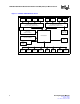
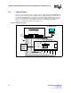
Table Of Contents
- 1.0 General Description
- 2.0 Introduction
- 3.0 Quick-Start Checklist
- 4.0 Optional Configurations
- 5.0 LEDs
- 6.0 Board Schematics
- Figure 4. LXD9785 PQFP MII Demo Board Power (Fiber Board Revision A2)
- Figure 5. Control
- Figure 6. MII Ports 0 and 1
- Figure 7. MII Ports 2 and 3
- Figure 8. MII Ports 4 and 5
- Figure 9. MII Ports 6 and 7
- Figure 10. Fiber Ports 0 and 1
- Figure 11. Fiber Ports 2 and 3
- Figure 12. Fiber Ports 4 and 5
- Figure 13. Fiber Ports 6 and 7
- Figure 14. Caps
- Figure 15. SS-SMII to MII ALTERA
- Figure 16. Clock Distribution
- Figure 17. Inter-Frame Status LEDs
- Figure 18. Logic Analyzer
- Figure 19. MDIO0 and MDC0 Fix
- Figure 20. MDIO1 and MDC1 Fix
- 7.0 Bill of Materials

LXD9785 PQFP Demo Board with FPGA for SS-SMII (Fiber)-to-MII Conversion
Development Kit Manual 7
Document #: 249323
Revision #: 003
Rev. Date: January 24, 2002
1.0 General Description
The LXD9785 PQFP MII Demo Board is an eight-port 100 Mbps Fast Ethernet Media Access Unit
(MAU) that provides a working platform for evaluation of the LXT9785/9785E Fast Ethernet
Octal Transceiver. All eight network ports provide a fiber interface for a 100BASE-FX connection.
The Demo Board allows system designers to test 100 Mbps Fiber link performance and register
functionality using a standard MII interface prior to board prototyping. Two FPGAs convert the
eight fiber (SS-SMII) interfaces on the LXT9785/9785E to eight standard MII interfaces. This
conversion simplifies evaluation of the LXT9785/9785E, rendering it compatible with existing MII
test equipment.
The Demo Board requires three external power supply inputs supplied by 2.5V and 3.3V power
supplies.
1.1 Features
• Eight independent IEEE 802.3-compliant 100BASE-FX ports.
• Quick setup, ease of use, and clear visibility of application settings for:
— Complete system demonstration.
— Individual circuit isolation.
• JTAG boundary scan.
• Two LED options for major functions:
— Configuration LEDs which can be controlled through register 20 (refer to the LXT9785/
9785E Datasheet).
— Inter Frame Status LED output controlled by FPGAs.
• Configurable via MDIO port or hardware jumpers.