
Computer Hardware User Manual
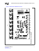
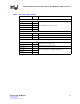
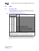
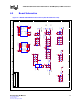
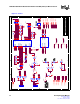
Table Of Contents
- 1.0 General Description
- 2.0 Introduction
- 3.0 Quick-Start Checklist
- 4.0 Optional Configurations
- 5.0 LEDs
- 6.0 Board Schematics
- Figure 4. LXD9785 PQFP MII Demo Board Power (Fiber Board Revision A2)
- Figure 5. Control
- Figure 6. MII Ports 0 and 1
- Figure 7. MII Ports 2 and 3
- Figure 8. MII Ports 4 and 5
- Figure 9. MII Ports 6 and 7
- Figure 10. Fiber Ports 0 and 1
- Figure 11. Fiber Ports 2 and 3
- Figure 12. Fiber Ports 4 and 5
- Figure 13. Fiber Ports 6 and 7
- Figure 14. Caps
- Figure 15. SS-SMII to MII ALTERA
- Figure 16. Clock Distribution
- Figure 17. Inter-Frame Status LEDs
- Figure 18. Logic Analyzer
- Figure 19. MDIO0 and MDC0 Fix
- Figure 20. MDIO1 and MDC1 Fix
- 7.0 Bill of Materials
LXD9785 PQFP Demo Board with FPGA for SS-SMII (Fiber)-to-MII Conversion
Development Kit Manual 17
Document #: 249323
Revision #: 003
Rev. Date: January 24, 2002
5.0 LEDs
5.1 Direct Drive LEDs
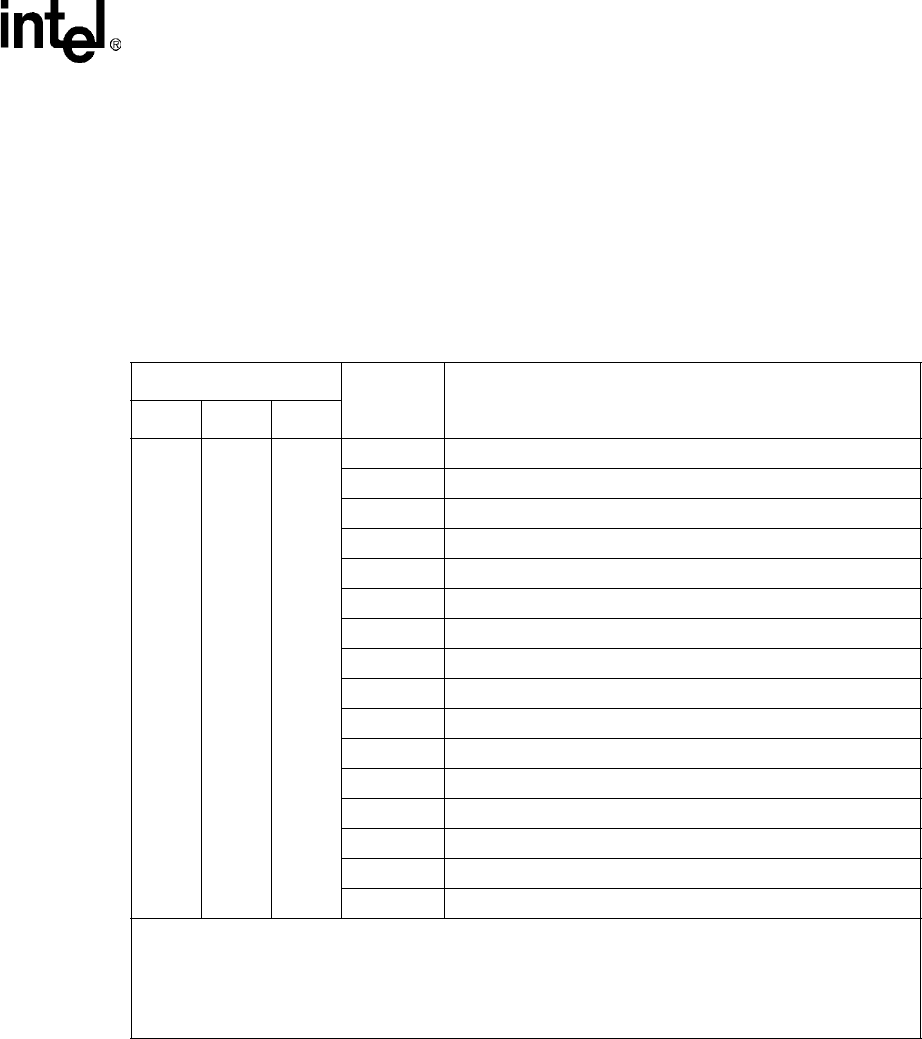
The LXD9785 PQFP MII Demo Board provides three programmable LED drivers per port (D4 -
D28). Each LED can display one of several available status conditions as selected by the LED
Configuration Register (Address 20) shown in Table 8.
.
The programmable LEDs (LED_1, LED_2, and LED_3) are set in the default mode and are
programmable via the MDIO pin. Register address 20 also provides optional LED pulse stretching
up to 100 ms. Register bits 20.3:2 select one of three possible stretch times as shown in Table 9 on
page 18.
Table 8. Direct Drive LED Configuration Settings (Register 20)
LED Bits
Program
Bits
Description
LED1 LED2 LED3
15:12 11:8 7:4
0000 Indicates 100 Mbps operation. (Default for LED1)
0001 Indicates transmit (Stretched).
0010 Indicates receive (stretched). (Default for LED3)
0011 Indicates collision (Stretched).
0100 Indicates active link (continuous). (Default for LED2)
0101 Indicates full-duplex.
0110 Reserved.
0111 Indicates transmit or receive activity.
1000 Test Mode. Turn LED on (continuous).
1001 Test Mode. Turn LED off (continuous).
1010 Test Mode. Blink LED fast (continuous).
1011 Test Mode. Blink LED slow (continuous).
1100 Indicates link and receive status combined
1
(Stretched)
2
.
1101 Indicates link and activity status combined
1
(Stretched)
2
.
1110 Indicates duplex and collision status combined
3
(Stretched)
2
.
1111 Reserved.
1. Link status is the primary LED driver. The LED is asserted (solid ON) when the link is up. The secondary
LED driver (receive, activity, or isolate) causes the LED to change state (blink).
2. Combined event LED settings are not affected by bit 20.1 (Pulse Stretch). These settings are stretched
regardless of the value of 20.1.
3. Duplex status is the primary LED driver. The LED is asserted (solid ON) when the link is full-duplex.
Collision status is the secondary LED driver. The LED changes state (blinks) when a collision occurs.