
Datasheet


Appendix E: POST Code Diagnostic LED Decoder Intel® Server Board S2600CW Family TPS
Revision1.11
178
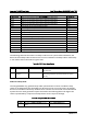
Checkpoint
Diagnostic LED Decoder
Description
1 = LED On, 0 = LED Off
Upper Nibble Lower Nibble
MSB
LSB
8h 4h 2h 1h 8h 4h 2h 1h
LED # #7 #6 #5 #4 #3 #2 #1 #0
A9h 1 0 1 0 1 0 0 1 DXE verifying SETUP password
ABh 1 0 1 0 1 0 1 1 DXE SETUP start
ACh 1 0 1 0 1 1 0 0 DXE SETUP input wait
ADh 1 0 1 0 1 1 0 1 DXE Ready to Boot
AEh 1 0 1 0 1 1 1 0 DXE Legacy Boot
AFh 1 0 1 0 1 1 1 1 DXE Exit Boot Services
B0h 1 0 1 1 0 0 0 0 RT Set Virtual Address Map Begin
B1h 1 0 1 1 0 0 0 1 RT Set Virtual Address Map End
B2h 1 0 1 1 0 0 1 0 DXE Legacy Option ROM init
B3h 1 0 1 1 0 0 1 1 DXE Reset system
B4h 1 0 1 1 0 1 0 0 DXE USB Hot plug
B5h 1 0 1 1 0 1 0 1 DXE PCI BUS Hot plug
B6h 1 0 1 1 0 1 1 0 DXE NVRAM cleanup
B7h 1 0 1 1 0 1 1 1 DXE Configuration Reset
00h 0 0 0 0 0 0 0 0 INT19
S3 Resume
E0h 1 1 1 0 0 0 0 0 S3 Resume PEIM (S3 started)
E1h 1 1 1 0 0 0 0 1 S3 Resume PEIM (S3 boot script)
E2h 1 1 1 0 0 0 1 0 S3 Resume PEIM (S3 Video Repost)
E3h 1 1 1 0 0 0 1 1 S3 Resume PEIM (S3 OS wake)
BIOS Recovery
F0h 1 1 1 1 0 0 0 0 PEIM which detected forced Recovery condition
F1h 1 1 1 1 0 0 0 1 PEIM which detected User Recovery condition
F2h 1 1 1 1 0 0 1 0 Recovery PEIM (Recovery started)
F3h 1 1 1 1 0 0 1 1 Recovery PEIM (Capsule found)
F4h 1 1 1 1 0 1 0 0 Recovery PEIM (Capsule loaded)
POST Memory Initialization MRC Diagnostic Codes
There are two types of POST Diagnostic Codes displayed by the MRC during memory
initialization: Progress Codes and Fatal Error Codes.
The MRC Progress Codes are displays to the Diagnostic LEDs that show the execution point in
the MRC operational path at each step.