
White Paper: LVDS Flat Panel Display Interface on Intel Desktop Boards


White Paper: LVDS on Intel Desktop Boards
8
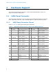
2.2.1 Backlight Inverter Power Connector Pinout
Refer to Table 4 for backlight inverter power header pinout definition.
Table 4. Backlight Inverter Power Header Pinout on
Select Intel Desktop Boards
Pin Signal Name Description
1 GND Ground
2 GND Ground
3 5 V/12 V Inverter power
4 5 V/12 V Inverter power
5 INV_RATING Inverter rating
6 BKLT_PWM Backlight PWM
7 BKLT_EN Backlight enable
2.2.2 Backlight Inverter Power Cable Recommendation
It is recommended that the cable used for connecting the onboard 7-pin backlight
inverter power header to the connector on the inverter board supports the current
rating per wire as required by the inverter board (up to 2 A per pin).
2.2.3 Backlight Inverter Power Voltage Selection
The board provides configurable voltage levels for powering diverse backlight inverter
boards.
Backlight inverter power header pins 3-4 can supply a voltage level of 5 V (default) or
12 V by properly setting the backlight inverter power voltage selection jumper,
comprised of a 1 x 3, 2.54-mm pitch red header with a black jumper, with 3 A rating
per pin.
Table 5 def
i
nes the configuration options for the backlight inverter power voltage
selection jumper.
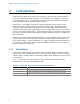
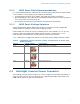
Table 5. Backlight Inverter Power Voltage Selection Jumper Configuration on
Select Intel Desktop Boards
Voltage Jumper Setting Configuration
5 V 1 and 2
Jumper position for 5 V (default)
12 V 3 and 2
Jumper position for 12 V