
White Paper: LVDS Flat Panel Display Interface on Intel Desktop Boards


White Paper: LVDS on Intel Desktop Boards
7
2.1.2 LVDS Panel Cable Recommendations
It is recommended that the cable used for connecting the onboard 30-pin LVDS header
to the connector on the display panel support the following:
• 15 twisted-pairs for data, clock, EDID, and panel logic power connectivity
• ground shielding in the cable harness for EMI protection as well as a path to ground
for 3.3 V/5 V/12 V power pins 25-28
• ground wire/connector from the shield for mounting hole attachment
2.1.3 LVDS Panel Voltage Selection
Select Intel Desktop Boards with LVDS interface connectivity provide configurable
voltage levels for powering a wide range of display panels.
LVDS header pins 25-28 can supply a voltage level of 3.3 V (default), 5 V or 12 V by
properly setting the LVDS panel voltage selection jumper, comprised of a 2 x 3,
2.00-mm pitch red header with a black jumper, keyed at pins 1 and 5.
Table 3 defi
nes the confi
guration options for the LVDS panel voltage selection jumper.
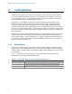
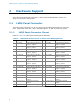
Table 3. LVDS Panel Voltage Selection Jumper Configuration on Select Intel
Desktop Boards
Voltage Jumper Setting Configuration
3.3 V 2 and 4
Jumper position for 3.3 V (default)
5 V 6 and 4
Jumper position for 5 V
12 V 3 and 4
Jumper position for 12 V
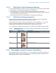
2.2 Backlight Inverter Power Connector
The backlight inverter power connector is a 7-pin (single-row) shrouded red header of
2.00-mm pitch and 2 A current rating per pin, supporting backlight lamp enable and
PWM control signals as well as inverter power.