
White Paper: LVDS Flat Panel Display Interface on Intel Desktop Boards


White Paper: LVDS on Intel Desktop Boards
6
2 Hardware Support
The LVDS flat panel display interface on select Intel Desktop Boards consists of a
group of connectors and jumpers.
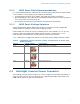
2.1 LVDS Panel Connector
The LVDS panel connector is a 30-pin (dual-row) shrouded white header of 1.00-mm
pitch, supporting video data, clock, and EDID signals, as well as panel logic power.
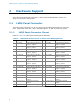
2.1.1 LVDS Panel Connector Pinout
Refer to Table 2 for LVDS panel header pinout definition.
Table 2. LVDS Panel Header Pinout on Select Intel Desktop Boards
Pin Signal Name Description Pin
Signal Name Description
1 LA_CLKN LVDS Channel A diff clock
output - negative
2 LB_CLKN LVDS Channel B diff clock
output - negative
3 LA_CLKP LVDS Channel A diff clock
output - positive
4 LB_CLKP LVDS Channel B diff clock
output - positive
5 EDID_3.3V Power for EDID ROM 6 EDID_GND Ground for EDID signals
7 LA_DATAN0 LVDS Channel A diff data
output – negative
8 LB_DATAN0 LVDS Channel B diff data
output – negative
9 LA_DATAP0 LVDS Channel A diff data
output – positive
10 LB_DATAP0 LVDS Channel B diff data
output – positive
11 LA_DATAN1 LVDS Channel A diff data
output – negative
12 LB_DATAN1 LVDS Channel B diff data
output – negative
13 LA_DATAP1 LVDS Channel A diff data
output – positive
14 LB_DATAP1 LVDS Channel B diff data
output – positive
15 GND Ground 16 GND Ground
17 LA_DATAN2 LVDS Channel A diff data
output – negative
18 LB_DATAN2 LVDS Channel B diff data
output – negative
19 LA_DATAP2 LVDS Channel A diff data
output – positive
20 LB_DATAP2 LVDS Channel B diff data
output – positive
21 GND Ground 22 GND Ground
23 GND Ground 24 GND Ground
25 3.3 V/5 V/12 V Selectable LCD power
output
26 3.3 V/5 V/12 V Selectable LCD power
output
27 3.3 V/5 V/12 V Selectable LCD power
output
28 3.3 V/5 V/12 V Selectable LCD power
output
29 EDID_CLK EDID/DDC clock signal 30 EDID_DATA EDID/DDC data signal