Intel® Desktop Board D945GCPE Technical Product Specification July 2007 Order Number: D98324-001US The Intel® Desktop Board D945GCPE may contain design defects or errors known as errata that may cause the product to deviate from published specifications. Current characterized errata are documented in the Intel Desktop Board D945GCPE Specification Update.
Revision History Revision Revision History Date -001 This is the first release of the Intel® Desktop Board D945GCPE Technical July 2007 Product Specification This product specification applies to only the standard Intel Desktop Board D945GCPE with BIOS identifier PE94510M.86A. Changes to this specification will be published in the Intel Desktop Board D945GCPE Specification Update before being incorporated into a revision of this document.
Preface This Technical Product Specification (TPS) specifies the board layout, components, connectors, power and environmental requirements, and the BIOS for the Intel® Desktop Board D945GCPE. It describes the standard product and available manufacturing options. Intended Audience The TPS is intended to provide detailed, technical information about the Desktop Board D945GCPE and its components to the vendors, system integrators, and other engineers and technicians who need this level of information.
Intel Desktop Board D945GCPE Technical Product Specification WARNING Warnings indicate conditions which, if not observed, can cause personal injury. Other Common Notation iv # Used after a signal name to identify an active-low signal (such as USBP0#). (NxnX) When used in the description of a component, N indicates component type, xn are the relative coordinates of its location on the Desktop Board D945GCPE, and X is the instance of the particular part at that general location.
Contents 1 Product Description 1.1 Overview........................................................................................ 10 1.1.1 Feature Summary ................................................................ 10 1.1.2 Board Layout ....................................................................... 12 1.1.3 Block Diagram ..................................................................... 14 1.2 Online Support................................................................................
Intel Desktop Board D945GCPE Technical Product Specification 2.5.1 Power Supply Considerations ................................................. 2.5.2 Fan Header Current Capability................................................ 2.5.3 Add-in Board Considerations .................................................. 2.6 Thermal Considerations .................................................................... 2.7 Reliability .....................................................................................
Contents Figures 1. 2. 3. 4. 5. 6. 7. 8. 9. 10. 11. 12. 13. 14. Board Components .......................................................................... Block Diagram ................................................................................ Back Panel Audio Connector Options .................................................. LAN Connector LED Locations ............................................................ Thermal Sensors and Fan Headers ....................................................
Intel Desktop Board D945GCPE Technical Product Specification 29. 30. 31. 32. 33. 34. 35. 36. 37. 38. viii Supervisor and User Password Functions............................................. Front-panel Power LED Blink Codes .................................................... BIOS Error Messages ....................................................................... Port 80h POST Code Ranges.............................................................. Port 80h POST Codes ................................
1 Product Description What This Chapter Contains 1.1 Overview........................................................................................ 10 1.2 Online Support................................................................................ 15 1.3 Processor ....................................................................................... 15 1.4 System Memory .............................................................................. 16 1.5 Intel® 945GC Chipset .........................
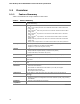
Intel Desktop Board D945GCPE Technical Product Specification 1.1 Overview 1.1.1 Feature Summary Table 1 summarizes the major features of the board. Table 1. Feature Summary Form Factor microATX (8.60 inches by 9.60 inches [218.44 millimeters by 243.
Product Description Table 1. Feature Summary (continued) Instantly Available PC Technology • Support for PCI Local Bus Specification Revision 2.
Intel Desktop Board D945GCPE Technical Product Specification 1.1.2 Board Layout Figure 1 shows the location of the major components. Figure 1. Board Components Table 2 lists the components identified in Figure 1.
Product Description Table 2.
Intel Desktop Board D945GCPE Technical Product Specification 1.1.3 Block Diagram Figure 2 is a block diagram of the major functional areas. Figure 2.
Product Description 1.2 Online Support To find information about… Visit this World Wide Web site: Intel® Desktop Board D945GCPE http://www.intel.com/products/motherboard/D945GCPE/index.htm Desktop Board Support http://support.intel.com/support/motherboards/desktop Available configurations for the Desktop Board D945GCPE http://www.intel.com/products/motherboard/D945GCPE/index.htm Supported processors http://www.intel.com/go/findcpu Chipset information http://www.intel.
Intel Desktop Board D945GCPE Technical Product Specification 1.4 System Memory The board has two DIMM sockets and supports the following memory features: • • • • • • • 1.8 V (only) DDR2 SDRAM DIMMs with gold-plated contacts Unbuffered, single-sided or double-sided DIMMs with the following restriction: Double-sided DIMMS with x16 organization are not supported. 2 GB maximum total system memory. Refer to Section 2.1.1 on page 34 for information on the total amount of addressable memory.
Product Description 1.4.1 Memory Configurations The Intel 82945GC GMCH supports two types of memory organization: • • Dual channel (Interleaved) mode. This mode offers the highest throughput for real world applications. Dual channel mode is enabled when the installed memory capacities of both DIMM channels are equal. Technology and device width can vary from one channel to the other but the installed memory capacity for each channel must be equal.
Intel Desktop Board D945GCPE Technical Product Specification ⎯ Texture color-keying/chroma-keying ⎯ Cubic environment reflection mapping • ⎯ Enhanced texture blending functions 3D Graphics Rendering enhancements ⎯ 1.3 Dual Texture GigaPixel/Sec Fill Rate ⎯ 16 and 32 bit color ⎯ Maximum 3D supported resolution of 1600 x 1200 x 32 at 85 Hz ⎯ Vertex cache ⎯ Anti-aliased lines • ⎯ OpenGL* version 1.
Product Description DVMT will always use a minimal fixed portion of system physical memory (as set in the BIOS Setup program) for compatibility with legacy applications. An example of this would be when using VGA graphics under DOS. Once loaded, the operating system and graphics drivers allocate additional system memory to the graphics buffer as needed for performing graphics functions. NOTE The use of DVMT requires operating system driver support. 1.5.1.
Intel Desktop Board D945GCPE Technical Product Specification 1.5.3.1 Parallel ATE IDE Interface The ICH7’s Parallel ATA IDE controller has one bus-mastering Parallel ATA IDE interface. The Parallel ATA IDE interface supports the following modes: • • • • • Programmed I/O (PIO): processor controls data transfer. 8237-style DMA: DMA offloads the processor, supporting transfer rates of up to 16 MB/sec.
Product Description For information about Refer to The location of the Serial ATA IDE connectors Figure 9, page 38 1.5.4 Real-Time Clock, CMOS SRAM, and Battery A coin-cell battery (CR2032) powers the real-time clock and CMOS memory. When the computer is not plugged into a wall socket, the battery has an estimated life of three years. When the computer is plugged in, the standby current from the power supply extends the life of the battery. The clock is accurate to ± 13 minutes/year at 25 ºC with 3.
Intel Desktop Board D945GCPE Technical Product Specification 1.7 Audio Subsystem The board supports the Intel High Definition audio subsystem based on the Realtek ALC662 audio codec. The audio subsystem supports the following features: • • • Line out and Mic in functions for front panel audio jacks A signal-to-noise (S/N) ratio of 95 dB Independent stereo audio playback from back panel connectors and Intel® High Definition audio front panel audio header.
Product Description Item Description A Line in B Line out C Mic in Figure 3. Back Panel Audio Connector Options For information about Refer to The back panel audio connectors Section 2.2.1, page 37 1.
Intel Desktop Board D945GCPE Technical Product Specification 1.8.2 Realtek RTL8101E-GR Fast Ethernet Controller The Realtek RTL8101E-GR provides the following functions: • • • • 10/100 Ethernet LAN connectivity Full device driver compatibility Programmable transit threshold Configuration EEPROM that contains the MAC address 1.8.2.1 RJ-45 LAN Connector with Integrated LEDs Two LEDs are built into the RJ-45 LAN connector (shown in Figure 4). Figure 4.
Product Description 1.9 Hardware Management Subsystem The hardware management features enable the board to be compatible with the Wired for Management (WfM) specification. The board has several hardware management features, including the following: • • • 1.9.
Intel Desktop Board D945GCPE Technical Product Specification 1.9.4 Thermal Monitoring Figure 5 shows the location of the sensors and fan headers. Item Description A Rear chassis fan B Thermal diode, located on processor die C Processor fan Figure 5.
Product Description 1.10 Power Management Power management is implemented at several levels, including: • • Software support through Advanced Configuration and Power Interface (ACPI) Hardware support: ⎯ Power connector ⎯ Fan headers ⎯ LAN wake capabilities ⎯ Instantly Available PC technology ⎯ Wake from USB ⎯ Wake from PS/2 devices ⎯ Power Management Event signal (PME#) wake-up support 1.10.
Intel Desktop Board D945GCPE Technical Product Specification 1.10.1.1 System States and Power States Under ACPI, the operating system directs all system and device power state transitions. The operating system puts devices in and out of low-power states based on user preferences and knowledge of how devices are being used by applications. Devices that are not being used can be turned off.
Product Description 1.10.1.3 Wake-up Devices and Events Table 7 lists the devices or specific events that can wake the computer from specific states. Table 7.
Intel Desktop Board D945GCPE Technical Product Specification NOTE The use of Wake from USB from an ACPI state requires an operating system that provides full ACPI support. 1.10.2.1 Power Connector ATX12V-compliant power supplies can turn off the system power through system control. When an ACPI-enabled system receives the correct command, the power supply removes all non-standby voltages.
Product Description 1.10.2.3 LAN Wake Capabilities CAUTION For LAN wake capabilities, the +5 V standby line for the power supply must be capable of providing adequate +5 V standby current. Failure to provide adequate standby current when implementing LAN wake capabilities can damage the power supply. LAN wake capabilities enable remote wake-up of the computer through a network. The LAN network adapter monitors network traffic at the Media Independent Interface.
Intel Desktop Board D945GCPE Technical Product Specification 1.10.2.5 Wake from USB USB bus activity wakes the computer from ACPI S1 or S3 states. NOTE Wake from USB requires the use of a USB peripheral that supports Wake from USB. 1.10.2.6 Wake from PS/2 Devices PS/2 device activity wakes the computer from an ACPI S1 or S3 state. 1.10.2.
2 Technical Reference What This Chapter Contains 2.1 2.2 2.3 2.4 2.5 2.6 2.7 2.8 Memory Resources .......................................................................... 34 Connectors and Headers................................................................... 36 Jumper Block .................................................................................. 46 Mechanical Considerations ................................................................ 48 Electrical Considerations .....................
Intel Desktop Board D945GCPE Technical Product Specification 2.1 2.1.1 Memory Resources Addressable Memory The board utilizes 2 GB of addressable system memory. Typically the address space that is allocated for PCI Conventional bus add-in cards, BIOS (SPI Flash), and chipset overhead resides above the top of DRAM (total system memory).
Technical Reference The amount of installed memory that can be used will vary based on add-in cards and BIOS settings. Figure 7 shows a schematic of the system memory map. All installed system memory can be used when there is no overlap of system addresses. Figure 7.
Intel Desktop Board D945GCPE Technical Product Specification 2.2 Connectors and Headers CAUTION Only the following connectors and headers have overcurrent protection: back panel USB, front panel USB, and PS/2. The other internal connectors/headers are not overcurrent protected and should connect only to devices inside the computer’s chassis, such as fans and internal peripherals. Do not use these connectors/headers to power devices external to the computer’s chassis.
Technical Reference 2.2.1 Back Panel Connectors Figure 8 shows the location of the back panel connectors. Item Description A PS/2 mouse port B PS/2 keyboard port C VGA port D USB ports [4] E LAN F Audio line in G Mic in H Audio line out Figure 8. Back Panel Connectors NOTE The back panel audio line out connector is designed to power headphones or amplified speakers only. Poor audio quality occurs if passive (non-amplified) speakers are connected to this output.
Intel Desktop Board D945GCPE Technical Product Specification 2.2.2 Component-side Connectors and Headers Figure 9 shows the locations of the component-side connectors and headers. Figure 9.
Technical Reference Table 8 lists the component-side connectors and headers identified in Figure 9. Table 8.
Intel Desktop Board D945GCPE Technical Product Specification Table 9.
Technical Reference Table 13. Processor Fan Header Pin Signal Name 1 Ground 2 +12 V 3 FAN_TACH 4 FAN_CONTROL Table 14. Chassis Fan Header Pin Signal Name 1 FAN_CONTROL 2 +12 V 3 FAN_TACH 2.2.2.1 Power Supply Connectors The board has the following power supply connectors: • • Main power – a 2 x 12 connector. This connector is compatible with 2 x 10 connectors previously used on Intel Desktop boards.
Intel Desktop Board D945GCPE Technical Product Specification Table 16. Processor Core Power Connector Pin Signal Name Pin Signal Name 1 Ground 2 Ground 3 +12 V 4 +12 V 2.2.2.2 Add-in Card Connectors The board has the following add-in card connectors: • PCI Conventional (rev 2.3 compliant) bus: two PCI Conventional bus add-in card connectors. The SMBus is routed to all PCI Conventional bus connectors.
Technical Reference 2.2.2.4 Front Panel Header This section describes the functions of the front panel header. Table 18 lists the signal names of the front panel header. Figure 10 is a connection diagram for the front panel header. Table 18.
Intel Desktop Board D945GCPE Technical Product Specification 2.2.2.4.1 Hard Drive Activity LED Header [Yellow] Pins 1 and 3 [Yellow] can be connected to an LED to provide a visual indicator that data is being read from or written to a hard drive. Proper LED function requires one of the following: • • A Serial ATA hard drive connected to an onboard Serial ATA connector An IDE hard drive connected to an onboard IDE connector 2.2.2.4.
Technical Reference 2.2.2.5 Front Panel USB Headers Figure 11 is a connection diagram for the front panel USB headers. # INTEGRATOR’S NOTES • • • • The +5 V DC power on the USB headers is fused. Pins 1, 3, 5, and 7 comprise one USB port. Pins 2, 4, 6, and 8 comprise one USB port. Use only a front panel USB connector that conforms to the USB 2.0 specification for high-speed USB devices. Figure 11.
Intel Desktop Board D945GCPE Technical Product Specification 2.3 Jumper Block CAUTION Do not move the jumper with the power on. Always turn off the power and unplug the power cord from the computer before changing a jumper setting. Otherwise, the board could be damaged. Figure 12 shows the location of the jumper block. The jumper block determines the BIOS Setup program’s mode. Table 21 describes the jumper settings for the three modes: normal, configure, and recovery.
Technical Reference Table 21. BIOS Setup Configuration Jumper Settings Function/Mode Jumper Setting Configuration 1-2 The BIOS uses current configuration information and passwords for booting. 2-3 After the POST runs, Setup runs automatically. The maintenance menu is displayed. None The BIOS attempts to recover the BIOS configuration. A recovery diskette is required.
Intel Desktop Board D945GCPE Technical Product Specification 2.4 2.4.1 Mechanical Considerations Form Factor The board is designed to fit into an ATX- or microATX-form-factor chassis. Figure 13 illustrates the mechanical form factor of the board. Dimensions are given in inches [millimeters]. The outer dimensions are 8.60 inches by 9.60 inches [218.44 millimeters by 243.84 millimeters]. Location of the I/O connectors and mounting holes are in compliance with the ATX specification. Figure 13.
Technical Reference 2.5 Electrical Considerations 2.5.1 Power Supply Considerations CAUTION The +5 V standby line from the power supply must be capable of providing adequate +5 V standby current. Failure to do so can damage the power supply. The total amount of standby current required depends on the wake devices supported and manufacturing options. Additional power required will depend on configurations chosen by the integrator.
Intel Desktop Board D945GCPE Technical Product Specification 2.5.2 Fan Header Current Capability CAUTION The processor fan must be connected to the processor fan header, not to a chassis fan header. Connecting the processor fan to a chassis fan header may result in onboard component damage that will halt fan operation. Table 23 lists the current capability of the fan headers. Table 23. Fan Header Current Capability Fan Header Maximum Available Current Processor fan 2.0 A Chassis fan 1.5 A 2.5.
Technical Reference CAUTION Ensure that the ambient temperature does not exceed the board’s maximum operating temperature. Failure to do so could cause components to exceed their maximum case temperature and malfunction. For information about the maximum operating temperature, see the environmental specifications in Section 2.8. CAUTION Ensure that proper airflow is maintained in the processor voltage regulator circuit. Failure to do so may result in damage to the voltage regulator circuit.
Intel Desktop Board D945GCPE Technical Product Specification Table 24 provides maximum case temperatures for the components that are sensitive to thermal changes. The operating temperature, current load, or operating frequency could affect case temperatures. Maximum case temperatures are important when considering proper airflow to cool the board. Table 24. Thermal Considerations for Components 2.
Technical Reference 2.8 Environmental Table 25 lists the environmental specifications for the board. Table 25.
Intel Desktop Board D945GCPE Technical Product Specification 54
3 Overview of BIOS Features What This Chapter Contains 3.1 3.2 3.3 3.4 3.5 3.6 3.7 3.8 3.9 3.1 Introduction ................................................................................... BIOS Flash Memory Organization ....................................................... Resource Configuration .................................................................... System Management BIOS (SMBIOS)................................................. BIOS Updates ...........................................
Intel Desktop Board D945GCPE Technical Product Specification Table 26 lists the BIOS Setup program menu features. Table 26.
Overview of BIOS Features 3.3.2 PCI IDE Support If you select Auto in the BIOS Setup program, the BIOS automatically sets up the PCI IDE connector with independent I/O channel support. The IDE interface supports hard drives up to ATA-66/100 and recognizes any ATAPI compliant devices, including CD-ROM drives, tape drives, and Ultra DMA drives. The interface also supports second-generation SATA drives.
Intel Desktop Board D945GCPE Technical Product Specification 3.5 BIOS Updates The BIOS can be updated using either of the following utilities, which are available on the Intel World Wide Web site: • • Intel® Express BIOS Update utility, which enables automated updating while in the Windows environment. Using this utility, the BIOS can be updated from a file on a hard disk, a 1.44 MB diskette, or a CD-ROM, or from the file location on the Web.
Overview of BIOS Features 3.6 Legacy USB Support Legacy USB support enables USB devices to be used even when the operating system’s USB drivers are not yet available. Legacy USB support is used to access the BIOS Setup program, and to install an operating system that supports USB. Legacy USB support operates as follows: 1. When you apply power to the computer, legacy support is disabled. 2. POST begins. 3.
Intel Desktop Board D945GCPE Technical Product Specification 3.7.3 Booting Without Attached Devices For use in embedded applications, the BIOS has been designed so that after passing the POST, the operating system loader is invoked even if the following devices are not present: • • • Video adapter Keyboard Mouse 3.7.4 Changing the Default Boot Device During POST Pressing the key during POST causes a boot device menu to be displayed.
Overview of BIOS Features 3.8 Adjusting Boot Speed These factors affect system boot speed: • • 3.8.1 Selecting and configuring peripherals properly Optimized BIOS boot parameters Peripheral Selection and Configuration The following techniques help improve system boot speed: • • • • 3.8.2 Choose a hard drive with parameters such as “power-up to data ready” less than eight seconds, that minimize hard drive startup delays. Select a CD-ROM drive with a fast initialization rate.
Intel Desktop Board D945GCPE Technical Product Specification 3.9 BIOS Security Features The BIOS includes security features that restrict access to the BIOS Setup program and who can boot the computer. A supervisor password and a user password can be set for the BIOS Setup program and for booting the computer, with the following restrictions: • • • • • • • The supervisor password gives unrestricted access to view and change all the Setup options in the BIOS Setup program. This is the supervisor mode.
4 Error Messages and Beep Codes What This Chapter Contains 4.1 BIOS Front-panel Power LED Codes.................................................... 63 4.2 BIOS Error Messages ....................................................................... 63 4.3 Port 80h POST Codes ....................................................................... 64 4.1 BIOS Front-panel Power LED Codes The front-panel power LED blinks off and on to display messages.
Intel Desktop Board D945GCPE Technical Product Specification 4.3 Port 80h POST Codes During the POST, the BIOS generates diagnostic progress codes (POST-codes) to I/O port 80h. If the POST fails, execution stops and the last POST code generated is left at port 80h. This code is useful for determining the point where an error occurred. Displaying the POST-codes requires a PCI bus add-in card, often called a POST card.
Error Messages and Beep Codes Table 33.
Intel Desktop Board D945GCPE Technical Product Specification Table 33.
Error Messages and Beep Codes Table 33.
Intel Desktop Board D945GCPE Technical Product Specification Table 34.
5 Regulatory Compliance and Battery Disposal Information What This Chapter Contains 5.1 Regulatory Compliance..................................................................... 69 5.2 Battery Disposal Information............................................................. 77 5.1 Regulatory Compliance This section contains the following regulatory compliance information for Desktop Board D945GCPE: • • • • • 5.1.
Intel Desktop Board D945GCPE Technical Product Specification 5.1.2 European Union Declaration of Conformity Statement We, Intel Corporation, declare under our sole responsibility that the product Intel® Desktop Board D945GCPE is in conformity with all applicable essential requirements necessary for CE marking, following the provisions of the European Council Directive 2004/108/EC (EMC Directive) and 2006/95/EC (Low Voltage Directive).
Regulatory Compliance and Battery Disposal Information Español Este producto cumple con las normas del Directivo Europeo 2004/108/EC & 2006/95/EC. Slovensky Tento produkt je v súlade s ustanoveniami európskych direktív 2004/108/EC a 2006/95/EC. Slovenščina Izdelek je skladen z določbami evropskih direktiv 2004/108/EC in 2006/95/EC. Svenska Denna produkt har tillverkats i enlighet med EG-direktiv 2004/108/EC & 2006/95/EC. Türkçe Bu ürün, Avrupa Birliği’nin 2004/108/EC ve 2006/95/EC yönergelerine uyar. 5.1.
Intel Desktop Board D945GCPE Technical Product Specification Deutsch Als Teil von Intels Engagement für den Umweltschutz hat das Unternehmen das Intel Produkt-Recyclingprogramm implementiert, das Einzelhandelskunden von Intel Markenprodukten ermöglicht, gebrauchte Produkte an ausgewählte Standorte für ordnungsgemäßes Recycling zurückzugeben. Details zu diesem Programm, einschließlich der darin eingeschlossenen Produkte, verfügbaren Standorte, Versandanweisungen, Bedingungen usw.
Regulatory Compliance and Battery Disposal Information Portuguese Como parte deste compromisso com o respeito ao ambiente, a Intel implementou o Programa de Reciclagem de Produtos para que os consumidores finais possam enviar produtos Intel usados para locais selecionados, onde esses produtos são reciclados de maneira adequada. Consulte o site http://www.intel.
Intel Desktop Board D945GCPE Technical Product Specification 5.1.3.3 Lead Free Desktop Board This Desktop Board is a European Union Restriction of Hazardous Substances (EU RoHS Directive 2002/95/EC) compliant product. EU RoHS restricts the use of six materials. One of the six restricted materials is lead. This Desktop Board is lead free although certain discrete components used on the board contain a small amount of lead which is necessary for component performance and/or reliability.
Regulatory Compliance and Battery Disposal Information 5.1.4 EMC Regulations Desktop Board D945GCPE complies with the EMC regulations stated in Table 37 when correctly installed in a compatible host system. Table 37. EMC Regulations Regulation Title FCC 47 CFR Part 15, Subpart B Title 47 of the Code of Federal Regulations, Part 15, Subpart B, Radio Frequency Devices. (USA) ICES-003 Issue 4 (Class B) Interference-Causing Equipment Standard, Digital Apparatus.
Intel Desktop Board D945GCPE Technical Product Specification Korean Class B statement translation: this is household equipment that is certified to comply with EMC requirements. You may use this equipment in residential environments and other non-residential environments. 5.1.5 Product Certification Markings (Board Level) Desktop Board D945GCPE has the product certification markings shown in Table 38: Table 38.
Regulatory Compliance and Battery Disposal Information 5.2 Battery Disposal Information CAUTION Risk of explosion if the battery is replaced with an incorrect type. Batteries should be recycled where possible. Disposal of used batteries must be in accordance with local environmental regulations. PRÉCAUTION Risque d'explosion si la pile usagée est remplacée par une pile de type incorrect. Les piles usagées doivent être recyclées dans la mesure du possible.
Intel Desktop Board D945GCPE Technical Product Specification PRECAUCIÓN Existe peligro de explosión si la pila no se cambia de forma adecuada. Utilice solamente pilas iguales o del mismo tipo que las recomendadas por el fabricante del equipo. Para deshacerse de las pilas usadas, siga igualmente las instrucciones del fabricante. WAARSCHUWING Er bestaat ontploffingsgevaar als de batterij wordt vervangen door een onjuist type batterij. Batterijen moeten zoveel mogelijk worden gerecycled.
Regulatory Compliance and Battery Disposal Information AWAS Risiko letupan wujud jika bateri digantikan dengan jenis yang tidak betul. Bateri sepatutnya dikitar semula jika boleh. Pelupusan bateri terpakai mestilah mematuhi peraturan alam sekitar tempatan. OSTRZEŻENIE Istnieje niebezpieczeństwo wybuchu w przypadku zastosowania niewłaściwego typu baterii. Zużyte baterie należy w miarę możliwości utylizować zgodnie z odpowiednimi przepisami ochrony środowiska.
Intel Desktop Board D945GCPE Technical Product Specification 80