
Computer Hardware User Manual

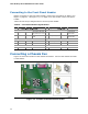


Table Of Contents
- Intel® Desktop Board D945GCLF Product Guide
- Revision History
- Preface
- Contents
- 1 Desktop Board Features
- 2 Installing and Replacing Desktop Board Components
- Before You Begin
- Installation Precautions
- Installing the I/O Shield
- Installing and Removing the Desktop Board
- Installing and Removing Memory
- Connecting the IDE Cable
- Connecting the Serial ATA (SATA) Cable
- Connecting Internal Headers
- Connecting a Chassis Fan
- Connecting Power Supply Cables
- Setting the BIOS Configuration Jumper
- Replacing the Battery
- 3 Updating the BIOS
- A BIOS Error Messages
- B Regulatory Compliance

Installing and Replacing Desktop Board Components
33
Connecting Power Supply Cables
CAUTION
Failure to use an appropriate power supply and/or not connecting the 12 V (2 x 2)
power connector to the Desktop Board may result in damage to the board or the
system may not function properly.
Figure 13 shows the location of the power connectors.
Figure 13. Connecting a 2 x 10 or 2 x 12 Power Supply Cable
1. Observe the precautions in "Before You Begin" on page 21.
2. Connect the 12 V processor core voltage power supply cable to the 2 x 2 connector
(Figure 13).
3. Connect the main power supply cable (2 x 10 or 2 x 12) to the 2 x 10 connector
(Figure 13).