
Computer Hardware User Manual

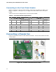


Table Of Contents
- Intel® Desktop Board D945GCLF Product Guide
- Revision History
- Preface
- Contents
- 1 Desktop Board Features
- 2 Installing and Replacing Desktop Board Components
- Before You Begin
- Installation Precautions
- Installing the I/O Shield
- Installing and Removing the Desktop Board
- Installing and Removing Memory
- Connecting the IDE Cable
- Connecting the Serial ATA (SATA) Cable
- Connecting Internal Headers
- Connecting a Chassis Fan
- Connecting Power Supply Cables
- Setting the BIOS Configuration Jumper
- Replacing the Battery
- 3 Updating the BIOS
- A BIOS Error Messages
- B Regulatory Compliance

Intel Desktop Board D945GCLF Product Guide
32
Connecting to the Front Panel Header
Before connecting to the front panel header, observe the precautions in "Before You
Begin" on page 21. See Figure 11, C on page 30 for the location of the front panel
header.
Table 6 shows the pin assignments for the front panel header.
Table 6. Front Panel Header Signal Names
Pin Signal In/Out Description Pin
Signal In/Out Description
Hard Drive Activity LED Power LED
1 HD_PWR Out
Hard disk LED pull-
up (330 Ω) to +5 V
2 HDR_BLNK_GRN Out
Front panel
green LED
3 HDA# Out
Hard disk active
LED
4 HDR_BLNK_YEL Out
Front panel
yellow LED
Reset Switch On/Off Switch
5 Ground Ground 6 SWITCH_ON# In Power switch
7 FP_RESET# In Reset switch 8 Ground Ground
Power Not Connected
9 +5 V Power 10 N/C No pin
Connecting a Chassis Fan
Figure 12 shows the location of the chassis fan header. Connect the chassis fan cable
to this header.
Figure 12. Location of the Chassis Fan Header