
Computer Hardware User Manual
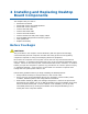

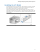


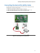

Table Of Contents
- Intel® Desktop Board D945GCLF Product Guide
- Revision History
- Preface
- Contents
- 1 Desktop Board Features
- 2 Installing and Replacing Desktop Board Components
- Before You Begin
- Installation Precautions
- Installing the I/O Shield
- Installing and Removing the Desktop Board
- Installing and Removing Memory
- Connecting the IDE Cable
- Connecting the Serial ATA (SATA) Cable
- Connecting Internal Headers
- Connecting a Chassis Fan
- Connecting Power Supply Cables
- Setting the BIOS Configuration Jumper
- Replacing the Battery
- 3 Updating the BIOS
- A BIOS Error Messages
- B Regulatory Compliance

Installing and Replacing Desktop Board Components
25
Installing and Removing Memory
NOTE
To be fully compliant with all applicable Intel SDRAM memory specifications, the
boards require DIMMs that support the Serial Presence Detect (SPD) data structure.
The Desktop Board has one 240-pin DDR2 DIMM socket.
Installing DIMMs
To make sure you have the correct DIMM, place it on the illustration in Figure 7
showing the DDR2 DIMM. All the notches should match the DDR2 DIMM.
Figure 7. Use DDR2 DIMMs