
Computer Hardware User Manual


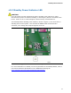

Table Of Contents
- Intel® Desktop Board D945GCLF Product Guide
- Revision History
- Preface
- Contents
- 1 Desktop Board Features
- 2 Installing and Replacing Desktop Board Components
- Before You Begin
- Installation Precautions
- Installing the I/O Shield
- Installing and Removing the Desktop Board
- Installing and Removing Memory
- Connecting the IDE Cable
- Connecting the Serial ATA (SATA) Cable
- Connecting Internal Headers
- Connecting a Chassis Fan
- Connecting Power Supply Cables
- Setting the BIOS Configuration Jumper
- Replacing the Battery
- 3 Updating the BIOS
- A BIOS Error Messages
- B Regulatory Compliance
Intel Desktop Board D945GCLF Product Guide
18
Power Management Features
Power management is implemented at several levels, including:
• Advanced Configuration and Power Interface (ACPI)
• Hardware support:
― Power connectors
― Fan headers
― +5 V standby power indicator LED
― LAN Wake capabilities
― Wake from USB
― Wake from PS/2 keyboard/mouse
― PME# wakeup support
ACPI
ACPI gives the operating system direct control over the power management and Plug
and Play functions of a computer. The use of ACPI with the Desktop Board requires an
operating system that provides full ACPI support.
Hardware Support
Power Connectors
The Desktop Board has two power connectors. See Figure 13 on page 33 for the
location of the power connectors.
Fan Headers
The Desktop Board has a 3-pin MCH fan header and a 3-pin chassis fan header. See
Figure 12 on page 32 for the location of the chassis fan header.