
Computer Hardware User Manual


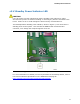

Table Of Contents
- Intel® Desktop Board D945GCLF Product Guide
- Revision History
- Preface
- Contents
- 1 Desktop Board Features
- 2 Installing and Replacing Desktop Board Components
- Before You Begin
- Installation Precautions
- Installing the I/O Shield
- Installing and Removing the Desktop Board
- Installing and Removing Memory
- Connecting the IDE Cable
- Connecting the Serial ATA (SATA) Cable
- Connecting Internal Headers
- Connecting a Chassis Fan
- Connecting Power Supply Cables
- Setting the BIOS Configuration Jumper
- Replacing the Battery
- 3 Updating the BIOS
- A BIOS Error Messages
- B Regulatory Compliance

Intel Desktop Board D945GCLF Product Guide
12
Processor
CAUTION
Failure to use an appropriate power supply and/or not connecting the 12 V (2 x 2)
power connector to the Desktop Board may result in damage to the board, or the
system may not function properly.
Desktop Board D945GCLF includes an Intel Atom processor 230. The processor is
soldered to the Desktop Board and is not customer upgradeable.
Main Memory
NOTE
To be fully compliant with all applicable Intel
®
SDRAM memory specifications, the
board should be populated with DIMMs that support the Serial Presence Detect (SPD)
data structure. If your DIMMs do not support SPD, you will see a notification to this
effect on the screen at power up. The BIOS will attempt to configure the memory
controller for normal operation.
The Desktop Board has one 240-pin Double Data Rate 2 (DDR2) SDRAM Dual Inline
Memory Module (DIMM) connector with gold-plated contacts. It supports:
• 533 MHz unbuffered, non-registered DDR2 DIMMs
• Serial Presence Detect (SPD) memory only
• Non-ECC memory
• Up to 2 GB of memory
For the latest list of tested memory, go to
http://support.intel.com/support/motherboards/desktop/
.