Intel® Desktop Board D865GBF/D865GLC Product Guide Order Number: C24485-001
Revision History Revision Revision History Date -001 First release of the Intel® Desktop Board D865GBF/D865GLC Product Guide. March 2003 If an FCC declaration of conformity marking is present on the board, the following statement applies: FCC Declaration of Conformity This device complies with Part 15 of the FCC Rules.
Preface This Product Guide gives information about board layout, component installation, BIOS Setup menus, and regulatory requirements for Intel® Desktop Board D865GBF/D865GLC. Intended Audience The Product Guide is intended for technically qualified personnel. It is not intended for general audiences. Information Layout The chapters in this Product Guide are arranged as follows: • 1 Desktop Board Features: a summary of product features.
Intel Desktop Boards D865GBF/D865GLC Product Guide Terminology The table below gives descriptions to some common terms used in the product guide.
Contents 1 Desktop Board Features Manufacturing Options ........................................................................................................11 Supported Operating Systems.............................................................................................11 Desktop Board Components................................................................................................12 Processor .............................................................................................
Intel Desktop Boards D865GBF/D865GLC Product Guide Installing the I/O Shield........................................................................................................28 Installing and Removing the Desktop Board ........................................................................29 Installing and Removing a Processor ..................................................................................30 Installing a Processor ...................................................................
Contents Chipset Configuration Submenu .................................................................................68 Fan Control Submenu.................................................................................................70 Hardware Monitoring Submenu ..................................................................................71 Security Menu .....................................................................................................................72 Power Menu ...........
Intel Desktop Boards D865GBF/D865GLC Product Guide 18. Back Panel Connectors.................................................................................................82 19. Audio Connectors .........................................................................................................83 20. PCI Bus Add-in Card and Peripheral Interface Connectors ...........................................84 Tables 1. 2. 3. 4. 5. 6. 7. 8. 9. 10. 11. 12. 13. 14. 15. 16. 17. 18. 19. 20. 21. 22. 23. 24. 25.
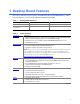
1 Desktop Board Features This chapter summarizes the main features of Intel® Desktop Board D865GBF/D865GLC. Table 1 shows the differences between Desktop Boards D865GBF and D865GLC. Table 1. Desktop Board Differences Feature Desktop Board D865GBF Desktop Board D865GLC Form factor ATX at 9.6-inches by 12.0-inches microATX at 9.6-inches by 9.6-inches PCI bus add-in card connectors Six Three Table 2 describes the major features of Desktop Board D865GBF/D865GLC. Table 2.
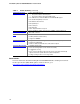
Intel Desktop Boards D865GBF/D865GLC Product Guide Table 2. Feature Summary (continued) Peripheral Interfaces • Up to eight USB 2.
Desktop Board Features Manufacturing Options Table 3 below describes the manufacturing options for Desktop Board D865GBF/D865GLC. Table 3.
Intel Desktop Boards D865GBF/D865GLC Product Guide Desktop Board Components Figure 1 shows the approximate location of the major components on Desktop Board D865GBF. Line In USB 2.0 Devices A B C USB 2.0 Devices D E F AA G Z Y H I X J W K V T U P R S O N M L Q OM15224 Figure 1. Desktop Board D865GBF Components NOTE Desktop board D865GLC has three PCI bus add-in card connectors.
Desktop Board Features Table 4.
Intel Desktop Boards D865GBF/D865GLC Product Guide Processor CAUTION Failure to use an ATX12V power supply, or not connecting the 12 V processor core voltage power supply connector to Desktop Board D865GBF/D865GLC may result in damage to the desktop board and/or power supply. Desktop Board D865GBF/D865GLC supports a single Intel Pentium 4 processor or Intel Celeron processor. Processors are not included with the desktop board and must be purchased separately.
Desktop Board Features Main Memory NOTE To be fully compliant with all applicable Intel® SDRAM memory specifications, the board should be populated with DIMMs that support the Serial Presence Detect (SPD) data structure. If your memory modules do not support SPD, you will see a notification to this effect on the screen at power up. The BIOS will attempt to configure the memory controller for normal operation.
Intel Desktop Boards D865GBF/D865GLC Product Guide Intel® 865G Chipset The Intel 865G chipset consists of the following devices: • Intel 82865G Graphics and Memory Controller Hub (GMCH) with AHA bus • Intel 82801EB I/O Controller Hub (ICH5) with AHA bus • Firmware Hub (FWH) Related Link: For more information about Intel 865G chipset, go to: http://developer.intel.com/design/nav/pcserver.
Desktop Board Features Related Links: Go to the following link or sections in this manual for more information about: • audio drivers and utilities, http://support.intel.
Intel Desktop Boards D865GBF/D865GLC Product Guide RJ-45 LAN Connector LEDs Two LEDs are built into the RJ-45 LAN connector. Table 6 describes the LED states when the board is powered up and the 10/100 Ethernet LAN subsystem is operating. Table 6. RJ-45 10/100 Ethernet LAN Connector LEDs LED Color LED State Indicates Green Off 10 Mbit/sec data rate is selected. On 100 Mbit/sec data rate is selected. Off LAN link is not established. On (steady state) LAN link is established.
Desktop Board Features Enhanced IDE Interface The ICH5’s IDE interface handles the exchange of information between the processor and peripheral devices like hard disks, CD-ROM drives, and Iomega Zip* drives inside the computer.
Intel Desktop Boards D865GBF/D865GLC Product Guide Security Passwords The BIOS includes security features that restrict whether the BIOS Setup program can be accessed and who can boot the computer. A supervisor password and a user password can be set for the Setup and for booting the computer, with the following restrictions: • The supervisor password gives unrestricted access to view and change all Setup options.
Desktop Board Features Fan Connectors The desktop board has two chassis fan connectors (Intel Precision Cooling Technology) and one processor fan connector. See Figure 15 on page 42 for the location of the fan connectors. Fan Speed Control (Intel® Precision Cooling Technology) Intel Precision Cooling Technology automatically adjusts the chassis fan speeds depending on the system’s temperature.
Intel Desktop Boards D865GBF/D865GLC Product Guide CR7J1 OM15225 Figure 2. Location of Standby Power Indicator CAUTION Power supplies used with this desktop board must be able to provide enough standby current to support the standard Instantly Available (ACPI S3 sleep state) configuration. If the standby current necessary to support multiple wake events from the PCI and/or USB buses exceeds power supply capacity, the desktop board may lose register settings stored in memory.
Desktop Board Features Wake from PS/2 Keyboard/Mouse PS/2 keyboard/mouse activity wakes the computer from an ACPI S1 or S3 state. PME# Wakeup Support When the PME# signal on the PCI bus is asserted, the computer wakes from an ACPI S1, S3, or S5 state. Speaker A speaker is mounted on the desktop board. The speaker provides audible error code (beep code) information during the Power-On Self-Test (POST).
Intel Desktop Boards D865GBF/D865GLC Product Guide 24
2 Installing and Replacing Desktop Board Components This chapter tells you how to: • Install the I/O shield • Install and remove the desktop board • Install and remove a processor and memory • Install and remove an AGP card • Connect the IDE and Serial ATA cables • Connect internal headers • Connecting 6-Channel Flex Audio with Jack Sensing • Connect hardware control and power cables • Set the BIOS configuration jumper • Clear passwords • Replace the battery Before You Begin WARNINGS The procedures in this
Intel Desktop Boards D865GBF/D865GLC Product Guide Installation Precautions When you install and test the Intel desktop board, observe all warnings and cautions in the installation instructions.
Installing and Replacing Desktop Board Components Chassis and Component Certifications Ensure that the chassis and certain components; such as the power supply, peripheral drives, wiring, and cables; are components certified for the country or market where used. Agency certification marks on the product are proof of certification. Typical product certifications include: • • • In Europe The CE marking signifies compliance with all applicable European requirements.
Intel Desktop Boards D865GBF/D865GLC Product Guide Installing the I/O Shield The desktop board comes with an I/O shield. When installed in the chassis, the shield blocks radio frequency transmissions, protects internal components from dust and foreign objects, and promotes correct airflow within the chassis. Install the I/O shield before installing the desktop board in the chassis. Place the shield inside the chassis as shown in Figure 3. Press the shield into place so that it fits tightly and securely.
Installing and Replacing Desktop Board Components Installing and Removing the Desktop Board WARNING Only qualified technical personnel should do this procedure. Disconnect the computer from its power source before performing the procedures described here. Failure to disconnect the power before you open the computer can result in personal injury or equipment damage. NOTE Refer to Appendix B for regulatory requirements.
Intel Desktop Boards D865GBF/D865GLC Product Guide Installing and Removing a Processor Instructions on how to install the processor to the desktop board are given below. Installing a Processor CAUTION Before installing or removing the processor, make sure that AC power has been removed by unplugging the power cord from the computer; the standby power LED should not be lit (see Figure 2 on page 22). Failure to do so could damage the processor and the board.
Installing and Replacing Desktop Board Components Connecting the Processor Fan Heat Sink Cable Connect the processor fan heat sink cable to the processor fan connector (see Figure 6). OM15229 Figure 6. Connecting the Processor Fan Heat Sink Cable to the Processor Fan Connector Removing the Processor For instruction on how to remove the processor fan heat sink and processor, refer to the processor installation manual or the Intel World Wide Web site at: http://support.intel.
Intel Desktop Boards D865GBF/D865GLC Product Guide Installing and Removing Memory CAUTION To be fully compliant with all applicable Intel SDRAM memory specifications, the boards require DIMMs that support the Serial Presence Detect (SPD) data structure. You can access the PC Serial Presence Detect Specification at: http://www.intel.
Installing and Replacing Desktop Board Components Installing DIMMs Before installing DIMMs, read and follow these guidelines for dual channel configuration. NOTE Performance Acceleration Technology (PAT) requires a processor with 800 MHz FSB frequency and DDR400 memory. Install a matched pair of DIMMs equal in speed, size, and technology (see Figure 8) in DIMM 0 in both channels A and B. Channel A 256 MB, 128 Mb, DDR400 DIMM 0 DIMM 1 Channel B 256 MB, 128 Mb, DDR400 DIMM 0 DIMM 1 Figure 8.
Intel Desktop Boards D865GBF/D865GLC Product Guide CAUTION Install memory in the DIMM sockets prior to installing an AGP video card to avoid interference with the memory retention mechanism. To install DIMMs, follow these steps: 1. Observe the precautions in “Before You Begin” on page 25. 2. Turn off all peripheral devices connected to the computer. Turn off the computer and disconnect the AC power cord. 3. Remove the computer’s cover and locate the DIMM sockets (see Figure 7). 4.
Installing and Replacing Desktop Board Components Installing and Removing an AGP Card CAUTION When installing any AGP card in the desktop board, ensure that it is fully seated in the AGP connector before you power on the system. If the card is not fully seated in the AGP connector, an electrical short may result across the AGP connector pins. Depending on the over-current protection of the power supply, certain board components and/or traces may be damaged. The AGP connector supports 0.
Intel Desktop Boards D865GBF/D865GLC Product Guide Connecting the IDE Cable The two IDE cables support the Ultra DMA-33 and ATA-66/100 transfer protocols. Each of the cables can connect two drives to the desktop board. Figure 11 shows the correct installation of the cable. NOTE ATA-66/100 compatible cables are backward compatible with drives using slower IDE transfer protocols.
Installing and Replacing Desktop Board Components Connecting the Serial ATA Cable The SATA cable (4-conductor) supports the Serial ATA protocol and connects a single drive to the desktop board. Either end of the cable can be connected to the SATA drive or the connector on the board (see Figure 12). For correct cable function: 1. Observe the precaution in “Before You Begin” on page 23. 2. Attach either cable end to the connector (A) on the board. 3. Attach either cable end to the connector (B) on the drive.
Intel Desktop Boards D865GBF/D865GLC Product Guide Connecting Internal Headers Figure 13 shows the location of internal headers. A 2 4 6 1 3 5 7 9 10 J9A2 B C 2 4 6 8 10 1 3 5 7 2 4 6 8 10 1 3 5 7 J9F1 J9H1 1 3 D 2 4 6 8 5 7 9 J9J1 E 1 2 OM15240 Item Description A Front panel audio B USB 2.0 C USB 2.0 D Front panel E Power LED Figure 13.
Installing and Replacing Desktop Board Components Installing a Front Panel Audio Solution Figure 13-A shows the location of the front panel audio header. Table 8 shows the pin assignments for the front panel audio header. Table 8.
Intel Desktop Boards D865GBF/D865GLC Product Guide Setting up the Flexible 6-Channel Audio with Jack Sensing After installing the SoundMAX 4 XL audio driver from the Intel Express Installer CD-ROM, the multi-channel audio feature can now be enabled. See Figure 14 for back panel audio connectors. A B C OM15694 Item A Description Rear left/right out or Line In B Front left/right out or S/PDIF line out C Center-LFE (Subwoofer) or Mic In Figure 14.
Installing and Replacing Desktop Board Components Connecting USB 2.0 Headers Before connecting USB 2.0 headers, observe the precautions in “Before You Begin” on page 25. Figure 13-A and -B on page 38 shows the location of the USB 2.0 headers. Table 9 shows the pin assignments for the headers. Table 9. USB 2.
Intel Desktop Boards D865GBF/D865GLC Product Guide Connecting Hardware Control and Power Cables Figure 15 shows the location of the chassis intrusion and fan headers, and power connectors. Chassis rear fan 1 J6B1 12 V processor core voltage connector 2 1 Processor fan 1 J6B1 Chassis intrusion connector Chassis front fan 1 Main power connector 2 1 1 J9H2 J7J3 OM15237 Figure 15.
Installing and Replacing Desktop Board Components Connecting the Chassis Intrusion Cable Connect the chassis intrusion cable to the header shown in Figure 15. Connecting Fans Connect the processor’s fan heat sink cable to the processor fan header on the board. Connect chassis fan cables to the board fan headers. See Figure 15 for fan header locations.
Intel Desktop Boards D865GBF/D865GLC Product Guide Setting the BIOS Configuration Jumper Block CAUTION Always turn off the power and unplug the power cord from the computer before changing the jumper. Moving the jumper with the power on may result in unreliable computer operation. The location of the desktop board’s BIOS configuration jumper is shown in Figure 16. 1 3 J9J4 OM15233 Figure 16.
Installing and Replacing Desktop Board Components Clearing Passwords This procedure assumes that the board is installed in the computer and the configuration jumper block is set to normal mode. 1. Observe the precautions in “Before You Begin” on page 25. 2. Turn off all peripheral devices connected to the computer. Turn off the computer. Disconnect the computer’s power cord from the AC power source (wall outlet or power adapter). 3. Remove the computer cover. 4.
Intel Desktop Boards D865GBF/D865GLC Product Guide Replacing the Battery A coin-cell battery (CR2032) powers the real-time clock and CMOS memory. When the computer is not plugged into a wall socket, the battery has an estimated life of three years. When the computer is plugged in, the standby current from the power supply extends the life of the battery. The clock is accurate to ± 13 minutes/year at 25 ºC with 3.3 VSB applied.
Installing and Replacing Desktop Board Components AVVERTIMENTO Esiste il pericolo di un esplosione se la pila non viene sostituita in modo corretto. Utilizzare solo pile uguali o di tipo equivalente a quelle consigliate dal produttore. Per disfarsi delle pile usate, seguire le istruzioni del produttore. PRECAUCIÓN Existe peligro de explosión si la pila no se cambia de forma adecuada. Utilice solamente pilas iguales o del mismo tipo que las recomendadas por el fabricante del equipo.
Intel Desktop Boards D865GBF/D865GLC Product Guide To replace the battery, follow these steps: 1. Observe the precautions in “Before You Begin” (see page 25). 2. Turn off all peripheral devices connected to the computer. Disconnect the computer’s power cord from the AC power source (wall outlet or power adapter). 3. Remove the computer cover. 4. Locate the battery on the board (see Figure 17). 5. With a medium flat-bladed screwdriver, gently pry the battery free from its connector.
3 Updating the BIOS This chapter tells you how to update the BIOS by either using the Intel® Express BIOS Update utility or the Iflash Memory Update utility, and how to recover the BIOS if an update fails. Updating the BIOS with the Intel® Express BIOS Update Utility With the Intel Express BIOS Update utility you can update the system BIOS while in the Windows environment.
Intel Desktop Boards D865GBF/D865GLC Product Guide Updating the BIOS with the Iflash Memory Update Utility With the Iflash Memory Update utility you can update the system BIOS from a floppy disk or other bootable media. The utility available from the Web provides a simple method for creating a bootable flash memory update floppy that will automatically update your BIOS. Obtaining the BIOS Update File You can update to a new version of the BIOS by using the BIOS update file.
Updating the BIOS Recovering the BIOS It is unlikely that anything will interrupt the BIOS update; however, if an interruption occurs, the BIOS could be damaged. The following steps explain how to recover the BIOS if an update fails. The following procedure uses recovery mode for the Setup program. See page 44 for more information on Setup modes. NOTE Because of the small amount of code available in the boot block area, there is no video support.
Intel Desktop Boards D865GBF/D865GLC Product Guide 52
4 Using the BIOS Setup Program The BIOS Setup program can be used to view and change the BIOS settings for the computer. The BIOS Setup program is accessed by pressing the key after the Power-On Self-Test (POST) memory test begins and before the operating system boot begins. NOTE The BIOS Setup menus described in this section may not show the latest settings.
Intel Desktop Boards D865GBF/D865GLC Product Guide Table 13 shows the function keys available for menu screens. Table 13.
Using the BIOS Setup Program Main Menu Main Advanced Security Power Boot BIOS Version xxxxx10A.86A.xxxx.xxx Processor Type Hyper-Threading Technology Processor Speed System Bus Speed System Memory Speed Intel(R) Pentium(R) 4 [Enabled] X.
Intel Desktop Boards D865GBF/D865GLC Product Guide Advanced Menu Main Advanced Security Power Boot Exit Setup Warning: Setting items on this screen to incorrect values may cause your system to malfunction! ` ` ` ` ` ` ` ` ` ` ` PCI Configuration Boot Configuration Peripheral Configuration IDE Configuration Diskette Configuration Event Log Configuration Video Configuration USB Configuration Chipset Configuration Fan Control Configuration Hardware Management m o n p Enter F1 P9 F10 ESC Select Screen
Using the BIOS Setup Program PCI Configuration Submenu Main Advanced Security Power Boot Exit PCI Configuration PCI PCI PCI PCI PCI Slot Slot Slot Slot Slot 1 2 3 4 5 IRQ IRQ IRQ IRQ IRQ Priority Priority Priority Priority Priority [Auto] m o n p Enter F1 P9 F10 ESC Select Screen Select Item Select ` Sub-Menu General Help Setup Defaults Save and Exit Exit The submenu shown in Table 17 is used to configure the IRQ priority of PCI slots individually. Table 17.
Intel Desktop Boards D865GBF/D865GLC Product Guide Boot Configuration Submenu Main Advanced Security Power Boot Exit Boot Configuration Plug & Play O/S Numlock [No] [On] m o n p Enter F1 P9 F10 ESC Select Screen Select Item Select ` Sub-Menu General Help Setup Defaults Save and Exit Exit The submenu shown in Table 18 is used to set the Plug & Play options and the power-on state of the Numlock key. Table 18.
Using the BIOS Setup Program Peripheral Configuration Submenu Main Advanced Security Power Boot Exit Peripheral Configuration Serial Port A Parallel Port Mode LAN Device Audio [Auto] [Auto] [Bi-directional] [Enabled] [Enabled] m o n p Enter F1 P9 F10 ESC Select Screen Select Item Select ` Sub-Menu General Help Setup Defaults Save and Exit Exit This submenu shown in Table 19 is used for configuring computer peripherals. Table 19.
Intel Desktop Boards D865GBF/D865GLC Product Guide Table 19. Peripheral Configuration Submenu (continued) Feature Options Description Mode • Output only • Bi-directional (default) Selects the mode for the parallel port. Not available if the parallel port is disabled. • EPP Output Only operates in AT*-compatible mode. • ECP Bi-directional operates in PS/2-compatible mode. EPP is Extended Parallel Port mode, a high-speed bi-directional mode.
Using the BIOS Setup Program ATA/IDE Configuration Submenu Main Advanced IDE Configuration Security ATA/IDE Configuration Legacy IDE Channels PCI IDE Bus Master Hard Disk Pre-Delay ` ` ` ` [PATA [PATA [PATA [PATA Primary Master Primary Slave Secondary Master Secondary Master Power Boot Exit [Legacy] [PATA Pri and Sec] [Enabled] [Disabled] : : : : xxxxxxx] Not Detected] xxxxxxx] Xxxxxxx] m o n p Enter F1 P9 F10 ESC Select Screen Select Item Select ` Sub-Menu General Help Setup Defaults Save and
Intel Desktop Boards D865GBF/D865GLC Product Guide PATA and SATA Submenus Main Advanced Security ` [SATA Port-0 : Type Maximum Capacity Power Boot Xxxxxxxx Exit ] [Auto] [Auto] Configuration Options Selected by BIOS LBA Mode : Block Mode: PIO Mode : Ultra DMA : Cable Detected : [Supported] 16 sectors Mode 4 Mode 6 Serial m o n p Enter F1 P9 F10 ESC Select Screen Select Item Select ` Sub-Menu General Help Setup Defaults Save and Exit Exit There are four IDE submenus: Primary master, primary s
Using the BIOS Setup Program Table 21. SATA and PATA Submenus (continued) Feature Options Description DMA Mode • Auto (default) Specifies the Ultra DMA mode for the drive. • SWDMA 0 • SWDMA 1 • SWDMA 2 • MWDMA 0 • MWDMA 1 • MWDMA 2 • UDMA 0 • UDMA 1 • UDMA 2 • UDMA 3 • UDMA 4 • UDMA 5 S.M.A.R.T. • Auto (default) Self-monitoring analysis and reporting technology.
Intel Desktop Boards D865GBF/D865GLC Product Guide Diskette Configuration Submenu Main Advanced Diskette Configuration Security Power Boot Diskette Controller [Enabled] Floppy A [1.44/1.25MB 3½"] Diskette Write Protect [Disabled] Exit m o n p Enter F1 P9 F10 ESC Select Screen Select Item Select ` Sub-Menu General Help Setup Defaults Save and Exit Exit This submenu shown in Table 22 is used to configure the floppy drive. Table 22.
Using the BIOS Setup Program Event Log Configuration Submenu Main Advanced Security Event Log Configuration Event Log Power Boot Exit [Space Available] View Event Log Clear Event Log Event Logging ECC Event Logging [Enabled] [Enabled] m o n p Enter F1 P9 F10 ESC Mark Events As Read Select Screen Select Item Select ` Sub-Menu General Help Setup Defaults Save and Exit Exit The submenu shown in Table 23 is used to configure the event logging features. Table 23.
Intel Desktop Boards D865GBF/D865GLC Product Guide Video Configuration Submenu Main Advanced Security Power Boot Exit Video Configuration AGP Aperture Size Primary Video Adapter Frame Buffer Size [ 64MB] [AGP] [1MB] m o n p Enter F1 P9 F10 ESC Select Screen Select Item Select ` SubMenu General Help Setup Defaults Save and Exit Exit The submenu shown in Table 24 is used to configure video features. Table 24.
Using the BIOS Setup Program USB Configuration Submenu Main Advanced Security Power Boot Exit USB Configuration High-Speed USB Legacy USB Support [Enabled] [Enabled] m o n p Enter F1 P9 F10 ESC Select Screen Select Item Select ` Sub-Menu General Help Setup Defaults Save and Exit Exit The submenu shown in Table 25 is used to configure USB features. Table 25.
Intel Desktop Boards D865GBF/D865GLC Product Guide Chipset Configuration Submenu Main Advanced Security Power Boot Exit Chipset Configuration Setup Warning: Setting items on this screen to incorrect values may cause your system to malfunction! ISA Enable Bit PCI Latency Timer CSA Device [Enabled] [32] [Auto] Do you wish to continue? Burn-In Mode [Continue] [Default] Extended Configuration Chipset Memory Timing Control Graphics Core Frequency SDRAM Frequency m o n p Enter F1 P9 F10 ESC [Default]
Using the BIOS Setup Program Table 25. Chipset Configuration Submenu (continued) Feature Options Description Extended Configuration • Default (default) Chooses the default or user defined settings for the extended configuration options. • User Defined Graphics Core Frequency • Auto (default) • 266 MHz Allows override of detected graphics core frequency value. • 333-320 MHz SDRAM Frequency • Auto (default) • 266 MHz Allows override of detected memory frequency value.
Intel Desktop Boards D865GBF/D865GLC Product Guide Fan Control Submenu Main Advanced Security Power Boot Exit Fan Control Configuration Setup Warning: These options will not take effect until power has been completely removed from the system. After saving the BIOS settings and turning the system off, unplug the power cord from the system and wait for at least 30 seconds before reapplying power and turning the system back on.
Using the BIOS Setup Program Hardware Monitoring Submenu Main Advanced Security Power Boot Exit Hardware Monitoring Note: These measurements are approximate and should not be used for validation purposes. Processor Zone Temperature System Zone 1 Temperature System Zone 2 Temperature 44oC/111oF 37oC/98oF 35oC/95oF Processor Fan Speed Rear Fan Speed (J1B1) Rear Fan Speed (J5B1) Front Fan Speed 2394 RPM 0 RPM 0 RPM 0 RPM +1.5Vin Vccp +3.3Vin +5Vin 12Vin 1.480 V 1.447 V 3.258 V 5.026 V 11.
Intel Desktop Boards D865GBF/D865GLC Product Guide Security Menu Main Advanced Supervisor Password User Password Security : : Power Boot Exit Not Installed Not Installed Set Supervisor Password Set User Password Chassis Intrusion [Disabled] m o n p Enter F1 P9 F10 ESC Select Screen Select Item Select ` Sub-Menu General Help Setup Defaults Save and Exit Exit The menu shown in Table 29 is used to set passwords and security features. Table 29.
Using the BIOS Setup Program Power Menu Main Advanced Security Power Boot Exit ` ACPI After Power Failure [Last State] The options below are not related to ACPI and may be ignored when shutting down using an ACPI OS. Wake on PCI PME [Stay Off] m o n p Enter F1 P9 F10 ESC Select Screen Select Item Select ` Sub-Menu General Help Setup Defaults Save and Exit Exit The menu shown in Table 30 is used to set power management features. Table 30.
Intel Desktop Boards D865GBF/D865GLC Product Guide ACPI Submenu Main Advanced Security Power Boot Exit Advanced Configuration and Power Interface ACPI Suspend State Wake on LAN from S5 [S1 State] [Stay Off] S1 is the safest mode but consumes more power. S3 consumes low power but drivers may not support this state.
Using the BIOS Setup Program Boot Menu Main Advanced Security Silent BOOT Intel ® Rapid BIOS Boot Scan User Flash Area PXE Boot to LAN USB Boot ` ` ` ` Power Boot Exit [Enabled] [Enabled] [Enabled] [Disabled] [Enabled] Boot Device Priority Hard Disk Drives Removable Devices ATAPI CD-ROM Drives m o n p Enter F1 P9 F10 ESC Select Screen Select Item Select ` Sub-Menu General Help Setup Defaults Save and Exit Exit The menu shown in Table 32 is used to set the boot features and the boot sequence.
Intel Desktop Boards D865GBF/D865GLC Product Guide Boot Device Priority Submenu Main Advanced Security st 1 Boot Device nd 2 Boot Device rd 3 Boot Device Power Boot st [1 FLOPPY DRIVE] [xxxxxxxxxxx] [xxxxxxxxxxx] Exit Specifies the boot sequence from the available devices. A device enclosed in parenthesis has been disabled in the corresponding type menu.
Using the BIOS Setup Program Hard Disk Drives Submenu Main st 1 nd 2 rd 3 th 4 Advanced Security Drive Drive Drive Drive Power Boot Exit [xxxxxxxxxxxxx] [xxxxxxxxxxxxx] [xxxxxxxxxxxxx] [xxxxxxxxxxxxx] Specifies the boot sequence from the available devices. Select the boot device with UpArrow or DownArrow key. Press Enter to set the selections as the intended boot device. ARMD = ATAPI Removable Media Device.
Intel Desktop Boards D865GBF/D865GLC Product Guide Removable Devices Submenu Main st 1 Advanced Security Drive Power [1 st Boot Exit FLOPPY DRIVE] Specifies the boot sequence from the available devices. Select the boot device with UpArrow or DownArrow key. Press Enter to set the selections as the intended boot device. ARMD = ATAPI Removable Media Device.
Using the BIOS Setup Program ATAPI CD-ROM Drives Main Advanced Security 1st Drive nd 2 Drive Power Boot Exit Specifies the boot sequence from the available devices. Select the boot device with UpArrow or DownArrow key. Press Enter to set the selections as the intended boot device. ARMD = ATAPI Removable Media Device.
Intel Desktop Boards D865GBF/D865GLC Product Guide Exit Menu Main Advanced Security Power Boot Exit Exit Saving Changes Exit Discarding Changes Load Optimal Defaults Load Custom Defaults Save Custom Defaults Discard Changes m o n p Enter F1 P9 F10 ESC Select Screen Select Item Select ` Sub-Menu General Help Setup Defaults Save and Exit Exit The menu shown in Table 37 is used to exit the BIOS Setup program, saving changes, and loading and saving defaults. Table 37.
5 Technical Reference Board Connectors This chapter shows the location of the: • • • Back panel connectors Audio connectors Add-in board and peripheral interface connectors CAUTION Many of the midboard and front panel connectors provide operating voltage (+5 V dc and +12 V dc, for example) to devices inside the computer chassis, such as fans and internal peripherals. These connectors are not overcurrent protected. Do not use these connectors for powering devices external to the computer chassis.
Intel Desktop Boards D865GBF/D865GLC Product Guide Back Panel Connectors NOTE The line out connector, located on the back panel, is designed to power either headphones or amplified speakers only. Poor audio quality may occur if passive (non-amplified) speakers are connected to this output. Figure 18 shows the back panel connectors. Line In USB 2.0 Devices USB 2.0 Devices OM15235 Figure 18.
Technical Reference Audio Connectors Figure 13 shows the approximate location of the audio connectors. C B A 2 4 6 1 3 5 7 9 1 2 3 4 J9C1 1 2 3 4 10 J9A2 J8B1 OM15236 Item Description A CD-ROM (ATAPI-style) B Front panel audio C Auxiliary line in (ATAPI-style) Figure 19.
Intel Desktop Boards D865GBF/D865GLC Product Guide Add-In Card and Peripheral Interface Connectors Figure 20 shows the PCI bus add-in card and peripheral interface connectors for Desktop Board D865GBF. Desktop Board D865GLC has three PCI bus add-in card connectors.
Technical Reference Desktop Board Resources Memory Map Table 38.
Intel Desktop Boards D865GBF/D865GLC Product Guide Interrupts Table 40.
A Error Messages and Indicators Desktop Board D865GBF/D865GLC reports POST errors in two ways: • By sounding a beep code • By displaying an error message on the monitor BIOS Beep Codes The BIOS beep codes are listed in Table 41. The BIOS also issues a beep code (one long tone followed by two short tones) during POST if the video configuration fails (a faulty video card or no card installed) or if an external ROM module does not properly checksum to zero. Table 41.
Intel Desktop Boards D865GBZ/D865GLC Product Guide BIOS Error Messages When a recoverable error occurs during the POST, the BIOS displays an error message describing the problem. Table 42. BIOS Error Messages Error Message Explanation GA20 Error An error occurred with Gate-A20 when switching to protected mode during the memory test. Pri Master HDD Error Pri Slave HDD Error Sec Master HDD Error Sec Slave HDD Error Could not read sector from corresponding drive.
Error Messages and Indicators Table 42. BIOS Error Messages (continued) Error Message Explanation Memory Size Decreased Memory size has decreased since the last boot. If no memory was removed, then memory may be bad. Memory Size Increased Memory size has increased since the last boot. If no memory was added, there may be a problem with the system. Memory Size Changed Memory size has changed since the last boot. If no memory was added or removed, then memory may be bad.
Intel Desktop Boards D865GBZ/D865GLC Product Guide 90
B Regulatory Compliance This appendix contains safety standards, electromagnetic compatibility (EMC) regulations, and product certification markings for Desktop Board D865GBF/D865GLC. Safety Regulations Desktop Board D865GBF/D865GLC complies with the safety regulations stated in Table 43 when correctly installed in a compatible host system. Table 43. Safety Regulations Regulation Title CSA C22.2 No.
Intel Desktop Boards D865GBZ/D865GLC Product Guide Product Certification Markings Desktop Board D865GBF/D865GLC has the following product certification markings: • UL joint US/Canada Recognized Component mark: consists of small c followed by a stylized backward UR and followed by a small US. Includes adjacent UL file number for Intel desktop boards: E210882 (component side). • FCC Declaration of Conformity logo mark for Class B equipment; includes Intel name and model designation (solder side).
Regulatory Compliance • Korean Class B statement translated as follows: this is household equipment that is certified to comply with EMC requirements. You may use this equipment in residential environments and other non-residential environments.
Intel Desktop Boards D865GBZ/D865GLC Product Guide 94