Intel® Desktop Board D845PESV Product Guide Order Number: A99406-002
Revision History Revision Revision History Intel® Date -001 First release of the Desktop Board D845PESV Product Guide. -002 Second release of the Intel Desktop Board D845PESV Product Guide. July 2002 August 2002 If an FCC declaration of conformity marking is present on the board, the following statement applies: FCC Declaration of Conformity This device complies with Part 15 of the FCC Rules.
Contents 1 Desktop Board Features Components......................................................................................................................... 9 Processor ............................................................................................................................10 Main Memory ......................................................................................................................11 Intel® 845PE Chipset......................................................
Intel Desktop Boards D845PESV Product Guide Connecting the Processor Fan Heat Sink Cable.........................................................25 Removing the Processor ............................................................................................25 Installing and Removing Memory ........................................................................................26 Installing DIMMs .........................................................................................................
Contents ATAPI CD-ROM Drives ..............................................................................................63 Exit Menu ............................................................................................................................64 5 Technical Reference Board Connectors ...............................................................................................................65 Back Panel Connectors ........................................................................
Intel Desktop Boards D845PESV Product Guide Tables 1. 2. 3. 4. 5. 6. 7. 8. 9. 10. 11. 12. 13. 14. 15. 16. 17. 18. 19. 20. 21. 22. 23. 24. 25. 26. 27. 28. 29. 30. 31. 32. 33. 34. 35. 36. 37. 38. vi Feature Summary .......................................................................................................... 7 Supported Processors ..................................................................................................10 RJ-45 LAN Connector LEDs ........................................
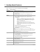
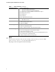
1 Desktop Board Features Table 1 describes the major features of Intel® Desktop Board D845PESV. Table 1. Feature Summary Form Factor • ATX at 12.0 inches by 8.2 inches Processor Support for: • 533/400 MHz front side bus (FSB) Intel® Pentium® 4 processor in an mPGA-478 socket • 400 MHz FSB Intel® Celeron® processor in an mPGA-478 socket Memory • Up to two 184-pin Double Data Rate (DDR) SDRAM Dual Inline Memory Modules (DIMMs) with gold-plated contacts.
Intel Desktop Board D845PESV Product Guide Table 1. Feature Summary (continued) Peripheral Interfaces • Up to six USB 2.
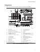
Desktop Board Features Components Figure 1 shows the location of the major components on Desktop Board D845PESV.
Intel Desktop Board D845PESV Product Guide Processor CAUTION Failure to use an ATX12V power supply, or not connecting the additional power supply lead to Desktop Board D845PESV may result in damage to the desktop board and/or power supply. Desktop Board D845PESV supports a single Intel Pentium 4 processor or Intel Celeron processor. Processors are not included with the desktop board and must be purchased separately. The processor connects to the Intel desktop board through the mPGA478-pin socket.
Desktop Board Features Main Memory ✏ NOTE To be fully compliant with all applicable Intel® SDRAM memory specifications, the board should be populated with DIMMs that support the Serial Presence Detect (SPD) data structure. If your memory modules do not support SPD, you will see a notification to this effect on the screen at power up. The BIOS will attempt to configure the memory controller for normal operation.
Intel Desktop Board D845PESV Product Guide Intel® 845PE Chipset The Intel 845PE chipset consists of the following devices: • • • Intel 82845PE Memory Controller Hub (MCH) with AHA bus Intel 82801DB I/O Controller Hub (ICH4) with AHA bus Firmware Hub (FWH) Intel® 82845PE Memory Controller Hub (MCH) The MCH provides the processor, system memory, AGP, and hub interfaces in the Intel 845PE chipset platform.
Desktop Board Features Input/Output (I/O) Controller The SMSC LPC47M172 or National Semiconductor PC87372 super I/O controllers feature the following: • • • • • • • • • Low pin count (LPC) interface Two serial ports (one via a board connector) One parallel port with Extended Capabilities Port (ECP) and Enhanced Parallel Port (EPP) support Serial IRQ interface compatible with serialized IRQ support for PCI systems PS/2-style mouse and keyboard interfaces Interface for one 1.2 MB, 1.44 MB, or 2.
Intel Desktop Board D845PESV Product Guide RJ-45 LAN Connector LEDs Two LEDs are built into the RJ-45 LAN connector. Table 3 describes the LED states when the board is powered up and the LAN subsystem is operating. Table 3. RJ-45 LAN Connector LEDs LED Color LED State Indicates Green Off 10 Mbit/sec data rate is selected. On 100 Mbit/sec data rate is selected. Yellow Off LAN link is not established. On (steady state) LAN link is established.
Desktop Board Features Expansion Slots Desktop Board D845PESV has the following add-in card connectors: • • Six PCI bus add-in card connectors (SMBus routed to PCI bus connector 2) One AGP connector Accelerated Graphics Port (AGP) ✏ NOTE Desktop Board D845PESV is only compatible with 1.5 V AGP cards. AGP is a high-performance interface for graphics-intensive applications, such as 3D graphics. AGP is independent of the PCI bus and is intended for exclusive use with graphical display devices.
Intel Desktop Board D845PESV Product Guide Security Passwords The BIOS includes security features that restrict whether the BIOS Setup program can be accessed and who can boot the computer. A supervisor password and a user password can be set for the Setup and for booting the computer, with the following restrictions: • • • The supervisor password gives unrestricted access to view and change all Setup options.
Desktop Board Features CR8H1 OM14704 Figure 2. Location of Standby Power Indicator CAUTION Power supplies used with this board must be able to provide enough standby current to support the standard Instantly Available (ACPI S3 sleep state) configuration. If the standby current necessary to support multiple wake events from the PCI and/or USB buses exceeds power supply capacity, the Intel desktop board may lose register settings stored in memory.
Intel Desktop Board D845PESV Product Guide Fan Connectors Desktop Board D845PESV has two chassis fan connectors and one processor fan connector. See Figure 11 on page 33 for the location of the fan connectors. Fan Speed Control (Intel® Precision Cooling) Intel Precision Cooling automatically adjusts the chassis fan speeds depending on the system’s temperature.
Desktop Board Features Battery A battery on the Intel desktop board keeps the values in CMOS RAM and the clock current when the computer is turned off. See Chapter 2 starting on page 21 for instructions on how to replace the battery. Real-Time Clock Desktop Board D845PESV has a time-of-day clock and 100-year calendar. A battery on the desktop board keeps the clock current when the computer is turned off.
Intel Desktop Board D845PESV Product Guide 20
2 Installing and Replacing Desktop Board Components This chapter tells you how to: • • • • • • • • • • • • • • Install the I/O shield Install and remove the desktop board Install and remove a processor Install and remove memory Install and remove an AGP card Connect the IDE cable Connect the front panel header Install the front panel audio solution Install the front panel USB solution Connect fans Connect power cables Set the BIOS configuration jumper block Clear passwords Replace the battery Before You B
Intel Desktop Board D845PESV Product Guide Installing the I/O Shield The Intel desktop board comes with an I/O shield. When installed in the chassis, the shield blocks radio frequency transmissions, protects internal components from dust and foreign objects, and promotes correct airflow within the chassis. Install the I/O shield before installing the desktop board in the chassis. Place the shield inside the chassis as shown in Figure 3. Press the shield into place so that it fits tightly and securely.
Installing and Replacing Desktop Board Components Installing and Removing the Desktop Board Refer to your chassis manual for instructions on installing and removing the Intel desktop board. WARNING Only qualified technical personnel should do this procedure. Disconnect the computer from its power source before performing the procedures described here. Failure to disconnect the power before you open the computer can result in personal injury or equipment damage.
Intel Desktop Board D845PESV Product Guide Installing and Removing a Processor Instructions on how to install the processor to the desktop board are given below. Installing a Processor CAUTION Before installing or removing the processor, make sure that AC power has been removed by unplugging the power cord from the computer; the standby power LED should not be lit (see Figure 2 on page 17). Failure to do so could damage the processor and the board. To install a processor, follow these instructions: 1.
Installing and Replacing Desktop Board Components Connecting the Processor Fan Heat Sink Cable Connect the processor fan heat sink cable to the processor fan connector (see Figure 6). OM14726 Figure 6. Connecting the Processor Fan Heat Sink Cable to the Processor Fan Connector Removing the Processor For instruction on how to remove the processor fan heat sink and processor, refer to the processor installation manual or the Intel World Wide Web site at: http://support.intel.
Intel Desktop Board D845PESV Product Guide Installing and Removing Memory CAUTION To be fully compliant with all applicable Intel SDRAM memory specifications, the board requires DIMMs that support the Serial Presence Detect (SPD) data structure. You can access the PC Serial Presence Detect Specification at: http://www.intel.com/technology/memory/pcsdram/spec/ Desktop Board D845PESV has two 184-pin DIMM sockets arranged as DIMM 0 and DIMM 1, as shown in Figure 7.
Installing and Replacing Desktop Board Components 5. Make sure the clips at either end of the DIMM socket(s) are pushed outward to the open position. 6. Holding the DIMM by the edges, remove it from its anti-static package. 7. Position the DIMM above the socket. Align the two small notches in the bottom edge of the DIMM with the keys in the socket (see inset in Figure 7). 8. Insert the bottom edge of the DIMM into the socket. 9.
Intel Desktop Board D845PESV Product Guide Installing an AGP Card Follow these instructions to install an AGP card: 1. Observe the precautions in "Before You Begin" on page 21. 2. Place the AGP card in the AGP connector. 3. Press down on the card until it is completely seated in the AGP connector and the card retention notch snaps into place around the RM pin. 4. Secure the card’s metal bracket to the chassis back panel with a screw.
Installing and Replacing Desktop Board Components Connecting the IDE Cable The Intel® boxed desktop board package includes two IDE cables. Either cable can connect two drives to the desktop board. The cables supports the Ultra DMA-33 and ATA-66/100 transfer protocols. Figure 9 shows the correct installation of the cable. ✏ NOTE ATA-66/100 compatible cables are backward compatible with drives using slower IDE transfer protocols.
Intel Desktop Board D845PESV Product Guide Connecting Front Panel Headers Figure 10 shows the location of the front panel headers. A B 1 3 5 7 9 1 3 5 7 2 4 6 10 2 4 6 8 10 3 1 1 2 HD LED Power LED D Reset On No Connection C Item Description A B C D Front panel audio Front panel USB 2.0 Front panel Alternate power/sleep LED Figure 10.
Installing and Replacing Desktop Board Components Connecting the Front Panel Header Before connecting the front panel header, observe the precautions in “Before You Begin” on page 21. Figure 10, C on page 30 shows the location of the front panel header. Table 4 shows the pin assignments for the front panel header. Table 4.
Intel Desktop Board D845PESV Product Guide To restore back panel operations, follow these steps: 1. Observe the precautions in “Before You Begin” on page 21. 2. Turn off all peripheral devices connected to the computer. Turn off the computer and disconnect the AC power cord. 3. Remove the cover. 4. Remove the front panel audio cable. 5. Install a jumper on pins 5-6 (rear R channel). 6. Install a jumper on pins 9-10 (rear L channel). 7. Replace the cover.
Installing and Replacing Desktop Board Components Connecting Fans and Power Cables Figure 11 shows the location of the fans and power supply connectors. 1 Chassis rear fan 12 V processor core voltage connector 1 Processor fan 1 3 Chassis front fan 1 3 Main power connector 1 OM14692 Figure 11. Location of Fans and Power Connectors Connecting Fans Connect the processor’s fan heat sink cable to the processor fan connector on the board. Connect the chassis fan cables to the board fan connectors.
Intel Desktop Board D845PESV Product Guide Setting the BIOS Configuration Jumper Block CAUTION Always turn off the power and unplug the power cord from the computer before changing the jumper. Moving the jumper with the power on may result in unreliable computer operation. The location of the desktop board’s BIOS configuration jumper is shown in Figure 12. 3 1 OM14693 Figure 12.
Installing and Replacing Desktop Board Components Clearing Passwords This procedure assumes that the board is installed in the computer and the configuration jumper block is set to normal mode. 1. Observe the precautions in “Before You Begin” on page 21. 2. Turn off all peripheral devices connected to the computer. Turn off the computer. Disconnect the computer’s power cord from the AC power source (wall outlet or power adapter). 3. Remove the computer cover. 4.
Intel Desktop Board D845PESV Product Guide Replacing the Battery A coin-cell battery (CR2032) powers the real-time clock and CMOS memory. When the computer is not plugged into a wall socket, the battery has an estimated life of three years. When the computer is plugged in, the standby current from the power supply extends the life of the battery. The clock is accurate to ± 13 minutes/year at 25 ºC with 3.3 VSB applied.
Installing and Replacing Desktop Board Components VORSICHT Bei falschem Einsetzen einer neuen Batterie besteht Explosionsgefahr. Die Batterie darf nur durch denselben oder einen entsprechenden, vom Hersteller empfohlenen Batterietyp ersetzt werden. Entsorgen Sie verbrauchte Batterien den Anweisungen des Herstellers entsprechend. (German) AVVERTIMENTO Esiste il pericolo di un esplosione se la pila non viene sostituita in modo corretto.
Intel Desktop Board D845PESV Product Guide To replace the battery, follow these steps: 1. Observe the precautions in “Before You Begin” (see page 21). 2. Turn off all peripheral devices connected to the computer. Disconnect the computer’s power cord from the AC power source (wall outlet or power adapter). 3. Remove the computer cover. 4. Locate the battery on the board (see Figure 13). 5. With a medium flat-bladed screwdriver, gently pry the battery free from its connector.
3 Updating the BIOS This chapter tells you how to update the BIOS by either using the Intel® Express BIOS Update utility or the Intel® Flash Memory Update Utility, and how to recover the BIOS if an update fails. Updating the BIOS with the Intel® Express BIOS Update Utility With the Intel Express BIOS Update utility you can update the system BIOS while in the Windows environment.
Intel Desktop Board D845PESV Product Guide Updating the BIOS with the Intel® Flash Memory Update Utility With the Intel Flash Memory Update Utility you can update the system BIOS from a floppy disk or other bootable media. The utility available from the Web provides a simple method for creating a bootable flash memory update floppy that will automatically update your BIOS. Obtaining the BIOS Update File You can update to a new version of the BIOS by using the BIOS update file.
Updating the BIOS Recovering the BIOS It is unlikely that anything will interrupt the BIOS update; however, if an interruption occurs, the BIOS could be damaged. The following steps explain how to recover the BIOS if an update fails. The following procedure uses recovery mode for the Setup program. See page 34 for more information on Setup modes. ✏ NOTE Because of the small amount of code available in the boot block area, there is no video support.
Intel Desktop Board D845PESV Product Guide 42
4 Using the BIOS Setup Program The BIOS Setup program can be used to view and change the BIOS settings for the computer. The BIOS Setup program is accessed by pressing the key after the Power-On Self-Test (POST) memory test begins and before the operating system boot begins. ✏ NOTE The BIOS Setup menus described in this section may not show the latest settings.
Intel Desktop Board D845PESV Product Guide Table 9 shows the function keys available for menu screens. Table 9.
Using the BIOS Setup Program Main Menu Maintenance Main Advanced Security Power Boot Exit Table 11 describes the Main Menu. This menu reports processor and memory information and is used to configure the system date and system time. Table 11. Main Menu Feature Options Description BIOS Version No options Displays the version of the BIOS. Processor Type No options Displays processor type. Processor Speed No options Displays processor speed.
Intel Desktop Board D845PESV Product Guide Advanced Menu Maintenance Main Advanced Security Power Boot Exit PCI Configuration Boot Configuration Peripheral Configuration IDE Configuration Diskette Configuration Event Log Configuration Video Configuration USB Configuration Chipset Configuration Table 12 describes the Advanced Menu. This menu is used to set advanced features that are available through the chipset. Table 12.
Using the BIOS Setup Program PCI Configuration Submenu Maintenance Main Advanced Security Power Boot Exit PCI Configuration Boot Configuration Peripheral Configuration IDE Configuration Diskette Configuration Event Log Configuration Video Configuration USB Configuration Chipset Configuration The submenu shown in Table 13 is used to configure the IRQ priority of PCI slots individually. Table 13.
Intel Desktop Board D845PESV Product Guide Boot Configuration Submenu Maintenance Main Advanced Security Power Boot Exit PCI Configuration Boot Configuration Peripheral Configuration IDE Configuration Diskette Configuration Event Log Configuration Video Configuration USB Configuration Chipset Configuration The submenu shown in Table 14 is used to set the Plug & Play options and the power-on state of the Numlock key. Table 14.
Using the BIOS Setup Program Peripheral Configuration Submenu Maintenance Main Advanced Security Power Boot Exit PCI Configuration Boot Configuration Peripheral Configuration IDE Configuration Diskette Configuration Event Log Configuration Video Configuration USB Configuration Chipset Configuration This submenu shown in Table 15 is used for configuring computer peripherals. Table 15.
Intel Desktop Board D845PESV Product Guide Table 15. Peripheral Configuration Submenu (continued) Feature Options Description Base I/O Address (This feature is present only when Parallel Port is set to Enabled) • 378 (default) Specifies the base I/O address for the parallel port, if Parallel Port is Enabled. Interrupt (This feature is present only when Parallel Port is set to Enabled) • IRQ 5 • IRQ 7 (default) Specifies the interrupt for the parallel port, if Parallel Port is Enabled.
Using the BIOS Setup Program IDE Configuration Submenu Maintenance Main Advanced Security Power Boot Exit PCI Configuration Boot Configuration Peripheral Configuration IDE Configuration Diskette Configuration Event Log Configuration Video Configuration USB Configuration Chipset Configuration This submenu shown in Table 16 is used to configure IDE device options. Table 16. IDE Configuration Submenu Feature Options Description IDE Controller • Disabled Specifies the integrated IDE controller.
Intel Desktop Board D845PESV Product Guide Primary/Secondary IDE Master/Slave Submenus Maintenance Main Advanced Security PCI Configuration Boot Configuration Peripheral Configuration IDE Configuration Diskette Configuration Event Log Configuration Video Configuration USB Configuration Chipset Configuration Power ➜ Boot Exit Primary IDE Master Primary IDE Slave Secondary IDE Master Secondary IDE Slave There are four IDE submenus: Primary master, primary slave, secondary master, and secondary slav
Using the BIOS Setup Program Table 17. Primary/Secondary IDE Master/Slave Submenus (continued) Feature Options Description DMA Mode • Auto (default) Specifies the Ultra DMA mode for the drive. • SWDMA 0 • SWDMA 1 • SWDMA 2 • MWDMA 0 • MWDMA 1 • MWDMA 2 • UDMA 0 • UDMA 1 • UDMA 2 • UDMA 3 • UDMA 4 Cable Detected (Note) • UDMA 5 None Displays the type of cable connected to the IDE interface: 40-conductor or 80-conductor (for ATA-66/100 devices).
Intel Desktop Board D845PESV Product Guide Diskette Configuration Submenu Maintenance Main Advanced Security Power Boot Exit PCI Configuration Boot Configuration Peripheral Configuration IDE Configuration Diskette Configuration Event Log Configuration Video Configuration USB Configuration Chipset Configuration This submenu shown in Table 18 is used to configure the floppy drive. Table 18.
Using the BIOS Setup Program Event Log Configuration Submenu Maintenance Main Advanced Security Power Boot Exit PCI Configuration Boot Configuration Peripheral Configuration IDE Configuration Diskette Configuration Event Log Configuration Video Configuration USB Configuration Chipset Configuration The submenu shown in Table 19 is used to configure the event logging features. Table 19.
Intel Desktop Board D845PESV Product Guide Video Configuration Submenu Maintenance Main Advanced Security Power Boot Exit PCI Configuration Boot Configuration Peripheral Configuration IDE Configuration Diskette Configuration Event Log Configuration Video Configuration USB Configuration Chipset Configuration The submenu shown in Table 20 is used to configure video features. Table 20.
Using the BIOS Setup Program USB Configuration Submenu Maintenance Main Advanced Security Power Boot Exit PCI Configuration Boot Configuration Peripheral Configuration IDE Configuration Diskette Configuration Event Log Configuration Video Configuration USB Configuration Chipset Configuration The menu shown in Table 21 is used to configure USB features. Table 21.
Intel Desktop Board D845PESV Product Guide Chipset Configuration Submenu Maintenance Main Advanced Security Power Boot Exit PCI Configuration Boot Configuration Peripheral Configuration IDE Configuration Diskette Configuration Event Log Configuration Video Configuration USB Configuration Chipset Configuration The menu shown in Table 22 is used to configure advanced chipset features. Table 22.
Using the BIOS Setup Program Table 22. Chipset Configuration Submenu (continued) Feature Options Description SDRAM CAS# Latency • • • • • • • • • • • Selects the number of clock cycles required to address a column in memory. SDRAM RAS# to CAS# delay SDRAM RAS# Precharge 2.5 2 Auto (default) 4 3 2 Auto (default) 4 3 2 Auto (default) Selects the number of clock cycles between addressing a row and addressing a column. Selects the length of time required before accessing a new row.
Intel Desktop Board D845PESV Product Guide Power Menu Maintenance Main Advanced Security Power Boot Exit The menu shown in Table 24 is used to set power management features. Table 24. Power Menu Feature Options Description ACPI No Options When selected, displays the ACPI submenu. After Power Failure • Stay Off • Last State (default) • Power On Determines the mode of operation if a power loss occurs. Stay Off keeps the power off until the power button is pressed.
Using the BIOS Setup Program Boot Menu Maintenance Main Advanced Security Power Boot Exit The menu shown in Table 26 is used to set the boot features and the boot sequence. Table 26. Boot Menu Feature Options Description Silent Boot • Disabled Disabled displays normal POST messages. • Enabled (default) Enabled displays OEM logo instead of POST messages. • Disabled Allows BIOS to skip certain tests while booting.
Intel Desktop Board D845PESV Product Guide Boot Device Priority Submenu Maintenance Main Advanced Security Power Boot Exit Boot Device Priority Hard Disk Drives Removable Devices ATAPI CD-ROM Drives The submenu represented in Table 27 is for setting boot devices priority. Table 27. Boot Device Priority Submenu Options Feature st 1 Boot Device nd 2 Boot Device rd 3 Boot Device Description • Removable Device Specifies the boot sequence from the available devices.
Using the BIOS Setup Program Removable Devices Submenu Maintenance Main Advanced Security Power Boot Exit Boot Device Priority Hard Disk Drives Removable Devices ATAPI CD-ROM Drives The submenu in shown Table 29 is for setting removable devices. Table 29. Removable Devices Submenu Feature st 1 Removable Device (Note) Options Description Dependent on installed removable devices Specifies the boot sequence from the available removable devices. To specify boot sequence: 1.
Intel Desktop Board D845PESV Product Guide Exit Menu Maintenance Main Advanced Security Power Boot Exit The menu shown in Table 31 is used to exit the BIOS Setup program, saving changes, and loading and saving defaults. Table 31. 64 Exit Menu Feature Description Exit Saving Changes Exits and saves the changes in CMOS SRAM. Exit Discarding Changes Exits without saving any changes made in the BIOS Setup program. Load Optimal Defaults Loads optimal defaults.
5 Technical Reference Board Connectors This chapter shows the location of the: • • • Back panel connectors Audio connectors Add-in board and peripheral interface connectors CAUTION Many of the midboard and front panel connectors provide operating voltage (+5 V dc and +12 V dc, for example) to devices inside the computer chassis, such as fans and internal peripherals. These connectors are not overcurrent protected. Do not use these connectors for powering devices external to the computer chassis.
Intel Desktop Board D845PESV Product Guide Back Panel Connectors Figure 14 shows the back panel connectors. A E G C B L K D F H I J OM14732 Item A Description PS/2 mouse port Color Green B PS/2 keyboard port Purple C USB 2.0 port 0 Black D USB 2.0 port 1 Black E Parallel port Burgundy F Serial port A Teal G RJ-45 (optional) Black H USB 2.0 port 2 Black I USB 2.0 port 3 Black J Mic in Pink K Audio line out Lime green L Audio line in Light blue Figure 14.
Technical Reference Audio Connectors Figure 15 shows the location of the audio connectors. A 1 3 5 7 9 2 4 6 B C 10 1 1 OM14733 Item Description Color A Front panel audio Black B Auxiliary line in (ATAPI) Light grey C CD-ROM (ATAPI) Black Figure 15.
Intel Desktop Board D845PESV Product Guide Add-In Card and Peripheral Interface Connectors Figure 16 shows the add-in card and peripheral interface connectors. A B C D E F G 40 39 40 39 2 1 2 1 2 1 J I H OM14735 Item Description Item Description A B C D E F G H I J PCI bus connector 6 PCI bus connector 5 PCI bus connector 4 PCI bus connector 3 PCI bus connector 2 (SMBus routed) 34 33 PCI bus connector 1 AGP Floppy drive Primary IDE Secondary IDE Figure 16.
Technical Reference Desktop Board Resources Memory Map Table 32.
Intel Desktop Board D845PESV Product Guide Interrupts Table 34.
A Error Messages and Indicators Desktop Board D845PESV reports POST errors in two ways: • • By sounding a beep code By displaying an error message on the monitor BIOS Beep Codes The BIOS beep codes are listed in Table 35. The BIOS also issues a beep code (one long tone followed by two short tones) during POST if the video configuration fails (a faulty video card or no card installed) or if an external ROM module does not properly checksum to zero. Table 35.
Intel Desktop Board D845PESV Product Guide BIOS Error Messages When a recoverable error occurs during the POST, the BIOS displays an error message describing the problem. Table 36. BIOS Error Messages Error Message Explanation GA20 Error An error occurred with Gate-A20 when switching to protected mode during the memory test. Pri Master HDD Error Pri Slave HDD Error Sec Master HDD Error Sec Slave HDD Error Could not read sector from corresponding drive.
Error Messages and Indicators Table 36. BIOS Error Messages (continued) Error Message Explanation Memory Size Decreased Memory size has decreased since the last boot. If no memory was removed, then memory may be bad. Memory Size Increased Memory size has increased since the last boot. If no memory was added, there may be a problem with the system. Memory Size Changed Memory size has changed since the last boot. If no memory was added or removed, then memory may be bad.
Intel Desktop Board D845PESV Product Guide 74
B Regulatory Compliance This appendix contains: • • Safety standards, electromagnetic compatibility (EMC) regulations, and product certification markings for Desktop Board D845PESV. Instructions and precautions for integrators who are installing the desktop board in a chassis. Safety Regulations Desktop Board D845PESV complies with the safety regulations stated in Table 37 when correctly installed in a compatible host system. Table 37. Safety Regulations Regulation Title CSA C22.2 No.
Intel Desktop Board D845PESV Product Guide Product Certification Markings Desktop Board D845PESV has the following product certification markings: • • • • • • • UL joint US/Canada Recognized Component mark: consists of small c followed by a stylized backward UR and followed by a small US. Includes adjacent UL file number for Intel desktop boards: E210882 (component side). FCC Declaration of Conformity logo mark for Class B equipment; includes Intel name and model designation (solder side).
Regulatory Compliance Installation Precautions When you install and test the desktop board, observe all warnings and cautions in the installation instructions.
Intel Desktop Board D845PESV Product Guide Chassis and Component Certifications Ensure that the chassis and certain components; such as the power supply, peripheral drives, wiring, and cables; are components certified for the country or market where used. Agency certification marks on the product are proof of certification. Typical product certifications include: In Europe The CE marking signifies compliance with all applicable European requirements.