Intel® Desktop Boards D845HV and D845WN Product Guide Order Number: A61038-001
Revision History Revision -001 Revision History First release of the Product Guide. Date Intel® Desktop Boards D845HV and D845WN July 2001 If an FCC declaration of conformity marking is present on the board, the following statement applies: FCC Declaration of Conformity This device complies with Part 15 of the FCC Rules.
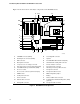
Contents 1 Desktop Board Features Components......................................................................................................................... 9 Processor ............................................................................................................................11 Main Memory ......................................................................................................................11 Intel® 845 Chipset .......................................................
Intel Desktop Boards D845HV and D845WN Product Guide Installing and Removing Memory ........................................................................................29 DIMM Installation Guidelines ......................................................................................29 Installing DIMMs .........................................................................................................29 Removing DIMMs ..............................................................................
Contents 5 Technical Reference Board Connectors ...............................................................................................................67 Back Panel Connectors ..............................................................................................68 Midboard Connectors .................................................................................................69 Front Panel Connectors........................................................................................
Intel Desktop Boards D845HV and D845WN Product Guide 21. 22. 23. 24. Power and Hardware Control Connectors.....................................................................70 D845HV Board Add-in Card and Peripheral Interface Connectors ................................71 D845WN Board Add-in Card and Peripheral Interface Connectors ...............................72 Front Panel Connectors ................................................................................................73 Tables 1. 2. 3. 4.
Desktop Board Features 1 Desktop Board Features ✏ NOTE The D845HV board layout was used for illustrations unless otherwise noted. Table 1 describes the major features of the boards. Table 1. Feature Summary Form Factors • microATX at 9.6 inches by 9.6 inches (D845HV board) • ATX at 12 inches by 9.6 inches (D845WN board) Processor • Support for an Intel® Pentium® 4 processor in an mPGA-478 socket Memory • Three SDRAM DIMM sockets. • Designed to support up to 3.
Intel Desktop Boards D845HV and D845WN Product Guide Table 1. Feature Summary (continued) Expansion Capabilities • D845HV board: Three PCI bus add-in card connectors One AGP connector One optional CNR connector (slot shared with PCI bus connector 3) • D845WN board: Six PCI bus add-in card connectors BIOS One AGP connector One optional CNR connector (slot shared with PCI bus connector 6) • Intel/AMI BIOS.
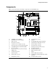
Desktop Board Features Components Figure 1 shows the location of the major components on the D845HV board.
Intel Desktop Boards D845HV and D845WN Product Guide Figure 2 shows the location of the major components on the D845WN board.
Desktop Board Features Processor CAUTION Failure to use an ATX12V power supply, or not connecting the additional power supply lead to the D845HV or D845WN boards may result in damage to the desktop board and/or power supply. The boards support a single Intel Pentium 4 processor. Processors are not included with the board and must be purchased separately. The processor connects to the board through the mPGA 478-pin socket.
Intel Desktop Boards D845HV and D845WN Product Guide • 64 Mbit, 128 Mbit, and 256 Mbit technologies for the following memory configurations: 32 MB to 384 MB (64 Mbit technology) Up to 768 MB (128 Mbit technology) Up to 1.5 GB (256 Mbit technology) ✏ NOTE The D845HV and D845WN desktop boards have been designed to support DIMMs based on 512 Mbit technology up to 3 GB, but this technology has not been validated on these boards.
Desktop Board Features Intel® 82801BA I/O Controller Hub (ICH2) The Intel 82801BA I/O Controller Hub integrates many I/O functions and provides the I/O subsystem with access to the rest of the platform. ICH2 features on D845HV and D845WN boards includes: • Integrated IDE controller supports two Ultra DMA-33 and ATA-66/100 channels, BMIDE and PIO modes • SMBus interface • FWH interface • Low Pin Count (LPC) interface • AC’97 2.
Intel Desktop Boards D845HV and D845WN Product Guide USB Support ✏ NOTE Computer systems that have an unshielded cable attached to a USB port might not meet FCC Class B requirements, even if no device or a low-speed USB device is attached to the cable. Use a shielded cable that meets the requirements for a full-speed USB device. The boards support up to seven USB 1.1 ports via the ICH2 and I/O controller; four ports routed to the back panel, two to the front panel connector, and one to the optional CNR.
Desktop Board Features Accelerated Graphics Port (AGP) ✏ NOTE The D845HV and D845WN boards are only compatible with 1.5 V AGP cards. AGP is a high-performance interface for graphics-intensive applications, such as 3D graphics. AGP is independent of the PCI bus and is intended for exclusive use with graphical display devices. The AGP connector supports 1.5 V AGP 4X and 2X add-in cards. The AGP card retention mechanism is used only with cards with retention notches (see Figure 12 on page 32).
Intel Desktop Boards D845HV and D845WN Product Guide IDE Auto Configuration If you install an IDE device (such as a hard drive) in your computer, the IDE auto-configuration utility in the BIOS automatically detects and configures the device for your computer. You do not need to run the BIOS Setup program after installing an IDE device. You can override the autoconfiguration options by specifying manual configuration in the BIOS Setup program.
Desktop Board Features RJ-45 LAN Connector LEDs Two LEDs are built into the RJ-45 LAN connector. Table 3 describes the LED states when the board is powered up and the LAN subsystem is operating. Table 3. RJ-45 LAN Connector LEDs LED Color LED State Indicates Green Off 10 Mbit/sec data rate is selected. On 100 Mbit/sec data rate is selected. Yellow Off LAN link is not established. On (steady state) LAN link is established.
Intel Desktop Boards D845HV and D845WN Product Guide Resume on Ring The operation of Resume on Ring can be summarized as follows: • Resumes operation from the ACPI S1 state • Requires only one call to access the computer • Detects incoming call similarly for external and internal modems • Requires modem interrupt be unmasked for correct operation Instantly Available Technology CAUTION For Instantly Available technology, the 5 V standby line for the power supply must be capable of delivering adequate +5 V
Desktop Board Features CAUTION If the standby current necessary to support multiple wake events from the PCI and/or USB buses exceeds power supply capacity, the desktop board may lose register settings stored in memory. Power supplies used with this board must be able to provide enough standby current to support the standard Instantly Available (ACPI S3 sleep state) configuration as outlined in Table 4. Values are determined by specifications such as PCI 2.2. Actual measurements may vary.
Intel Desktop Boards D845HV and D845WN Product Guide ✏ NOTE PCI requirements are calculated by totaling the following: • One wake-enabled device @ 375 mA. • Five non wake-enabled devices @ 20 mA each. PS/2 Ports requirements per the IBM PS/2 Port Specification (Sept 1991): • Keyboard @ 275 mA. • Mouse @ 70 mA. USB requirements are calculated by totaling the following: • • • • 20 One wake-enabled device @ 500 mA. USB hub @ 100 mA. Three USB non-wake-enabled devices @ 2.5 mA each.
2 Installing and Replacing Desktop Board Components This chapter tells you how to: • Install the I/O shield • Install and remove the desktop board • Install and remove a processor • Install and remove memory • Install and remove an AGP retention mechanism and card • Connect the IDE cable • Set the BIOS jumper • Clear passwords • Replace the battery Before You Begin CAUTION Before you install this board in a chassis, see Appendix B for regulatory requirements and precautions.
Intel Desktop Boards D845HV and D845WN Product Guide Installing the I/O Shield The board comes with an I/O shield. When installed in the chassis, the shield blocks radio frequency transmissions, protects internal components from dust and foreign objects, and promotes correct airflow within the chassis. Install the I/O shield before installing the board in the chassis. Place the shield inside the chassis as shown in Figure 4. Press the shield into place so that it fits tightly and securely.
Installing and Replacing Desktop Board Components Installing and Removing the Desktop Board Refer to your chassis manual for instructions on installing and removing the board. The D845HV board is secured to the chassis by eight screws and the D845WN board by 11 screws. See Figure 5 and Figure 6 for the locations of the mounting holes of each board. WARNING This procedure should be done only by qualified technical personnel.
Intel Desktop Boards D845HV and D845WN Product Guide Figure 6 shows the location of the mounting holes for the D850WN board. OM12080 Figure 6.
Installing and Replacing Desktop Board Components Installing and Removing a Processor Instructions on how to install the processor fan heatsink retention mechanism (RM) base and processor to the desktop board are given below. For instruction on how to install the processor fan heatsink, refer to the processor installation manual or the Intel World Wide Web site: http://support.intel.
Intel Desktop Boards D845HV and D845WN Product Guide 3. Align the four fasteners (B) of the processor fan heatsink RM base with the corresponding holes in the desktop board (C). Gently press the base down until all four corners snap into place. Verify that all four fasteners are fully engaged, then press down each of the four locking pushpins (A) to fully secure the base to the desktop board (see Figure 8). A B C OM12096 Figure 8.
Installing and Replacing Desktop Board Components Installing a Processor CAUTION Before installing or removing the processor, make sure that ac power has been removed by unplugging the power cord from the computer; the standby power LED should not be lit (see Figure 3 on page 18). Failure to do so could damage the processor and the board. To install a processor, follow these instructions: 1. Observe the precautions in “Before You Begin” on page 21. 2.
Intel Desktop Boards D845HV and D845WN Product Guide Connecting the Processor Fan Heatsink Cable Connect the processor fan heatsink cable to the processor fan connector (see Figure 10). OM12083 Figure 10. Connecting the Processor Fan Heatsink Cable to the Processor Fan Connector Removing a Processor For instruction on how to remove the processor fan heatsink, refer to the processor installation manual or the Intel World Wide Web site at: http://support.intel.
Installing and Replacing Desktop Board Components Installing and Removing Memory CAUTION To be fully compliant with all applicable Intel® SDRAM memory specifications, the boards require DIMMs that support the Serial Presence Detect (SPD) data structure. You can access the PC Serial Presence Detect Specification at: http://www.intel.com/technology/memory/pcsdram/spec/ The boards have three 168-pin DIMM sockets arranged as banks 0, 1, and 2 as shown in Figure 11.
Intel Desktop Boards D845HV and D845WN Product Guide 0 1 2 OM11986 Figure 11. Installing a Memory Module 5. Make sure the clips at either end of the DIMM socket(s) are pushed outward to the open position. 6. Holding the DIMM by the edges, remove it from its anti-static package. 7. Position the DIMM above the socket. Align the two small notches in the bottom edge of the DIMM with the keys in the socket (see inset in Figure 11). 8. Insert the bottom edge of the DIMM into the socket. 9.
Installing and Replacing Desktop Board Components Removing DIMMs To remove a memory module, follow these steps: 1. Observe the precautions in "Before You Begin" on page 21. 2. Turn off all peripheral devices connected to the computer. Turn off the computer. 3. Remove the ac power cord from the computer. 4. Remove the computer’s cover. 5. Remove the AGP card (if it interferes with the DIMM clips from being easily opened and closed). 6. Gently spread the retaining clips at each end of the DIMM socket.
Intel Desktop Boards D845HV and D845WN Product Guide Installing and Removing the AGP Retention Mechanism and Card The AGP connector supports 1.5 V 4X and 2X AGP cards. Newer cards have a retention notch as shown in Figure 12. When using notched cards, install the AGP card retention mechanism (RM) before installing a card. The AGP card RM is not used with unnotched cards.
Installing and Replacing Desktop Board Components The AGP card RM (see Figure 13) encloses the board’s AGP connector and stabilizes the AGP card. Place the board (component side up) on a flat, supportive surface, preferably on the anti-static bag in which the board was shipped. Follow the steps outlined below to attach the RM (A) to the AGP connector (B): 1. Locate the AGP connector (J5E1) on the board as shown below.
Intel Desktop Boards D845HV and D845WN Product Guide Installing an AGP Card Follow these instructions to install an AGP card: 1. Place the AGP card in the AGP connector. 2. Press down on the card until it is completely seated in the AGP connector and the card retention notch snaps into place around the RM pin. 3. Secure the card’s metal bracket to the chassis back panel with a screw. Removing the AGP Card from the Retention Mechanism Follow these instructions to remove the AGP card from the RM: 1.
Installing and Replacing Desktop Board Components Removing the AGP Card Retention Mechanism Follow these instructions to remove the AGP card retention mechanism: 1. Using diagonal cutters (A), cut the loop (B) joining the two sides of the retention mechanism (see Figure 15). 2. Spread the sides of the retention mechanism (C) and lift the retention mechanism off of the AGP connector. ✏ NOTE Once removed using this method, the AGP RM cannot be reused. B c A c OM10593 Figure 15.
Intel Desktop Boards D845HV and D845WN Product Guide Connecting the IDE Cable The Intel® boxed desktop board package includes two IDE cables. Both are capable of connecting two drives to the desktop board. The 40-contact cable supports the Ultra DMA-33 transfer protocol. The 40-contact, 80-conductor cable supports ATA-66 and ATA-100 transfer protocols and is backward compatible with drives using slower IDE transfer protocols. Figure 16 shows the correct installation of the cable.
Installing and Replacing Desktop Board Components Setting the BIOS Configuration Jumper Block CAUTION Always turn off the power and unplug the power cord from the computer before changing the jumper. Moving the jumper with the power on may result in unreliable computer operation. The location of the board’s BIOS configuration jumper is shown in Figure 17. 1 3 J9G1 OM11996 Figure 17.
Intel Desktop Boards D845HV and D845WN Product Guide Clearing Passwords This procedure assumes that the board is installed in the computer and the configuration jumper block is set to normal mode. 1. Observe the precautions in “Before You Begin” on page 21. 2. Turn off all peripheral devices connected to the computer. Turn off the computer. Disconnect the computer’s power cord from the ac power source (wall outlet or power adapter). 3. Remove the computer cover. 4.
Installing and Replacing Desktop Board Components Replacing the Battery A coin-cell battery (CR2032) powers the real-time clock and CMOS memory. When the computer is not plugged into a wall socket, the battery has an estimated life of three years. When the computer is plugged in, the standby current from the power supply extends the life of the battery. The clock is accurate to ± 13 minutes/year at 25 ºC with 3.3 VSB applied.
Intel Desktop Boards D845HV and D845WN Product Guide VORSICHT Bei falschem Einsetzen einer neuen Batterie besteht Explosionsgefahr. Die Batterie darf nur durch denselben oder einen entsprechenden, vom Hersteller empfohlenen Batterietyp ersetzt werden. Entsorgen Sie verbrauchte Batterien den Anweisungen des Herstellers entsprechend. (German) AVVERTIMENTO Esiste il pericolo di un esplosione se la pila non viene sostituita in modo corretto.
Installing and Replacing Desktop Board Components To replace the battery, follow these steps: 1. Observe the precautions in “Before You Begin” (see page 21). 2. Turn off all peripheral devices connected to the computer. Disconnect the computer’s power cord from the ac power source (wall outlet or power adapter). 3. Remove the computer cover. 4. Locate the battery on the board (see Figure 18). 5. With a medium flat-bladed screwdriver, gently pry the battery free from its connector.
Intel Desktop Boards D845HV and D845WN Product Guide 42
3 Updating the BIOS This chapter tells you how to update the BIOS by either using the Intel® Express BIOS Update utility or the Intel® Flash Memory Update Utility, and how to recover the BIOS if an update fails. Updating the BIOS with the Intel® Express BIOS Update Utility With the Intel Express BIOS Update utility you can update the system BIOS while in the Windows environment.
Intel Desktop Boards D845HV and D845WN Product Guide Updating the BIOS with the Intel® Flash Memory Update Utility With the Intel Flash Memory Update Utility you can update the system BIOS from a floppy disk or other bootable media. The utility available from the Web provides a simple method for creating a bootable flash memory update floppy that will automatically update your BIOS. Obtaining the BIOS Update File You can update to a new version of the BIOS by using the BIOS update file.
Updating the BIOS Recovering the BIOS It is unlikely that anything will interrupt the BIOS update; however, if an interruption occurs, the BIOS could be damaged. The following steps explain how to recover the BIOS if an update fails. The following procedure uses recovery mode for the Setup program. See page 37 for more information on Setup modes. ✏ NOTE Because of the small amount of code available in the boot block area, there is no video support.
Intel Desktop Boards D845HV and D845WN Product Guide 46
4 Using the Setup Program The BIOS Setup program can be used to view and change the BIOS settings for the computer. The BIOS Setup program is accessed by pressing the key after the Power-On Self-Test (POST) memory test begins and before the operating system boot begins. ✏ NOTE The BIOS Setup menus described in this section may not show the latest settings.
Intel Desktop Boards D845HV and D845WN Product Guide Table 7 shows the function keys available for menu screens. Table 7.
Using the Setup Program Extended Configuration Submenu Maintenance Main Advanced Security Power Boot Exit Extended Configuration This submenu shown in Table 9 is used to set system control and video memory cache mode. This submenu becomes available when User Defined is selected under Extended Configuration. Table 9. Extended Configuration Submenu Feature Options Description Extended Configuration • Default (default) User Defined allows setting memory control and video memory cache mode.
Intel Desktop Boards D845HV and D845WN Product Guide Main Menu Maintenance Main Advanced Security Power Boot Exit Table 10 describes the Main Menu. This menu reports processor and memory information and is used to configure the system date and system time. Table 10. Main Menu Feature Options Description BIOS Version No options Displays the version of the BIOS. Processor Type No options Displays processor type. Processor Speed No options Displays processor speed.
Using the Setup Program Advanced Menu Maintenance Main Advanced Security PCI Configuration Power Boot Exit Boot Configuration Peripheral Configuration IDE Configuration Diskette Configuration Event Log Configuration Video Configuration Table 11 describes the Advanced Menu. This menu is used to set advanced features that are available through the chipset. Table 11.
Intel Desktop Boards D845HV and D845WN Product Guide PCI Configuration Submenu Maintenance Main Advanced Security Power Boot Exit PCI Configuration Boot Configuration Peripheral Configuration IDE Configuration Diskette Configuration Event Log Configuration Video Configuration The submenu shown in Table 12 is used to configure the IRQ priority of PCI slots individually. Table 12.
Using the Setup Program Boot Configuration Submenu Maintenance Main Advanced Security Power Boot Exit PCI Configuration Boot Configuration Peripheral Configuration IDE Configuration Diskette Configuration Event Log Configuration Video Configuration The submenu shown in Table 13 is used to set the Plug & Play options, reset configuration data, and the power-on state of the Numlock key. Table 13.
Intel Desktop Boards D845HV and D845WN Product Guide Peripheral Configuration Submenu Maintenance Main Advanced Security Power Boot Exit PCI Configuration Boot Configuration Peripheral Configuration IDE Configuration Diskette Configuration Event Log Configuration Video Configuration This submenu shown in Table 14 is used for configuring computer peripherals. Table 14. Peripheral Configuration Submenu Feature Options Description Serial Port A • Disabled Configures serial port A.
Using the Setup Program Table 14. Peripheral Configuration Submenu (continued) Feature Options Description Parallel Port • Disabled Configures the parallel port. • Enabled Auto assigns LPT1 the address 378h and the interrupt IRQ7. • Auto (default) An * (asterisk) displayed next to an address indicates a conflict with another device. Mode • Output Only • Bi-directional (default) Selects the mode for the parallel port. Not available if the parallel port is disabled.
Intel Desktop Boards D845HV and D845WN Product Guide IDE Configuration Submenu Maintenance Main Advanced Security Power Boot Exit PCI Configuration Boot Configuration Peripheral Configuration IDE Configuration Diskette Configuration Event Log Configuration Video Configuration This submenu shown in Table 15 is used to configure IDE device options. Table 15. IDE Configuration Submenu Feature Options Description IDE Controller • Disabled Specifies the integrated IDE controller.
Using the Setup Program Primary/Secondary IDE Master/Slave Submenus Maintenance Main Advanced Security Power Boot Exit Boot Configuration Peripheral Configuration IDE Configuration ➜ Primary IDE Master Diskette Configuration Primary IDE Slave Event Log Configuration Secondary IDE Master Video Configuration Secondary IDE Slave There are four IDE submenus: Primary master, primary slave, secondary master, and secondary slave. Table 16 shows the format of these IDE submenus.
Intel Desktop Boards D845HV and D845WN Product Guide Table 16. Primary/Secondary IDE Master/Slave Submenus (continued) Feature Options Description Ultra DMA • Disabled (default) Specifies the Ultra DMA mode for the drive. • Mode 0 • Mode 1 • Mode 2 • Mode 3 • Mode 4 Cable Detected (Note) None Displays the type of cable connected to the IDE interface: 40-conductor or 80-conductor (for ATA-66/100 devices). Note: These configuration options appear only if an IDE device is installed.
Using the Setup Program Event Log Configuration Submenu Maintenance Main Advanced Security Power Boot Exit PCI Configuration Boot Configuration Peripheral Configuration IDE Configuration Diskette Configuration Event Log Configuration Video Configuration The submenu shown in Table 18 is used to configure the event logging features. Table 18. Event Log Configuration Submenu Feature Options Description Event Log No options Indicates if there is space available in the event log.
Intel Desktop Boards D845HV and D845WN Product Guide Video Configuration Submenu Maintenance Main Advanced Security Power Boot Exit PCI Configuration Boot Configuration Peripheral Configuration IDE Configuration Diskette Configuration Event Log Configuration Video Configuration The submenu shown in Table 19 is used to configure video features. Table 19.
Using the Setup Program Security Menu Maintenance Main Advanced Security Power Boot Exit The menu shown in Table 20 is used to set passwords and security features. Table 20. Security Menu If no password entered previously: Feature Options Description Supervisor Password Is No options Reports if there is a supervisor password set. User Password Is No options Reports if there is a user password set. Set Supervisor Password Password can be up to seven Specifies the supervisor password.
Intel Desktop Boards D845HV and D845WN Product Guide Power Menu Maintenance Main Advanced Security Power Boot Exit The menu shown in Table 21 is used to set power management features. Table 21. Power Menu Feature Options Description ACPI No Options When selected, displays the ACPI submenu. After Power Failure • Stays Off Specifies the mode of operation if an ac power loss occurs. • Last State (default) • Power On Stays Off keeps the power off until the power button is pressed.
Using the Setup Program Boot Menu Maintenance Main Advanced Security Power Boot Exit The menu shown in Table 24 is used to set the boot features and the boot sequence. Table 23. Boot Menu Feature Options Description Quiet Boot • Disabled Disabled displays normal POST messages. • Enabled (default) Enabled displays OEM graphic instead of POST messages. • Disabled Enables the computer to boot without running certain POST tests.
Intel Desktop Boards D845HV and D845WN Product Guide Boot Device Priority Submenu Maintenance Main Advanced Security Boot Power Exit Boot Device Priority Hard Disk Drives Removable Devices ATAPI CD-ROM Drives The submenu represented in Table 24 is for setting boot devices priority. Table 24. Boot Device Priority Submenu Feature st 1 Boot Device nd 2 Boot Device Options Description • Removable Device Specifies the boot sequence from the available types of boot devices.
Using the Setup Program Hard Disk Drives Submenu Maintenance Main Advanced Security Power Boot Exit Boot Device Priority Hard Disk Drives Removable Devices ATAPI CD-ROM Drives The submenu shown in Table 25 is for setting hard disk drives. Table 25. Hard Disk Drives Submenu Feature Options Description Dependent on installed hard drives Specifies the boot sequence from the available hard disk drives. To specify boot sequence: st 1 Hard Disk Drive (Note) 1.
Intel Desktop Boards D845HV and D845WN Product Guide ATAPI CD-ROM Drives Maintenance Main Advanced Security Power Boot Exit Boot Device Priority Hard Disk Drives Removable Devices ATAPI CD-ROM Drives The submenu shown in Table 27 is for setting ATAPI CD-ROM drives. Table 27. ATAPI CD-ROM Drives Submenu Feature Options Description Dependent on installed ATAPI CD-ROM drives Specifies the boot sequence from the available ATAPI CD-ROM drives.
5 Technical Reference Board Connectors The board connectors can be divided into three groups: • • Back panel connectors Midboard connectors Audio connectors Power and hardware connectors • Add-in board and peripheral interface connectors Front panel connectors CAUTION Many of the midboard and front panel connectors provide operating voltage (+5 V dc and +12 V dc, for example) to devices inside the computer chassis, such as fans and internal peripherals.
Intel Desktop Boards D845HV and D845WN Product Guide Back Panel Connectors Figure 19 shows the back panel connectors on the board.
Technical Reference Midboard Connectors Audio Connectors Figure 20 shows the location of the audio connectors. A B C 4 1 4 1 12 9 10 OM11991 Item Description Color A Front panel audio Black B CD-ROM (ATAPI) Black C Auxiliary line in (ATAPI) White Figure 20.
Intel Desktop Boards D845HV and D845WN Product Guide Power and Hardware Connectors CAUTION Failure to use an ATX12V power supply, or not connecting the additional power supply lead to the D845HV or D845WN board may result in damage to the desktop board. The D845HV and D845WN boards require an ATX12V compliant power supply to function according to desktop board specifications.
Technical Reference Add-In Card and Peripheral Interface Connectors Figure 22 shows the add-in card and peripheral interface connectors for the D845HV board. A B C D E 40 2 1 39 40 2 1 2 1 34 33 39 H G F OM11993 Item Description Item Description A B C D CNR (optional) PCI bus connector 3 PCI bus connector 2 PCI bus connector 1 E F G H AGP Diskette drive Primary IDE Secondary IDE Figure 22.
Intel Desktop Boards D845HV and D845WN Product Guide Figure 23 shows the add-in card and peripheral interface connectors for the D845WN board. A B C D E F G H 40 2 1 39 40 2 1 2 1 34 33 39 K J I OM12041 Item Description Item Description A B C D E F CNR (optional) PCI bus connector 6 PCI bus connector 5 PCI bus connector 4 PCI bus connector 3 PCI bus connector 2 G H I J K PCI bus connector 1 AGP Diskette drive Primary IDE Secondary IDE Figure 23.
Technical Reference Front Panel Connectors Figure 24 shows the location of the front panel connectors. 12 9 10 10 2 1 16 7 15 1 2 1 A B C D OM11994 Item Description A Front panel B Alternate power/sleep LED C Front panel USB D Front panel audio Figure 24.
Intel Desktop Boards D845HV and D845WN Product Guide Desktop Board Resources Memory Map Table 29.
Technical Reference I/O Map Table 31.
Intel Desktop Boards D845HV and D845WN Product Guide Table 31.
Technical Reference Interrupts Table 32.
Intel Desktop Boards D845HV and D845WN Product Guide 78
A Error Messages and Indicators The D845HV and D845WN boards report POST errors in two ways: • By sounding a beep code • By displaying an error message on the monitor BIOS Beep Codes The BIOS beep codes are listed in Table 33. The BIOS also issues a beep code (one long tone followed by two short tones) during POST if the video configuration fails (a faulty video card or no card installed) or if an external ROM module does not properly checksum to zero. Table 33.
Intel Desktop Boards D845HV and D845WN Product Guide BIOS Error Messages When a recoverable error occurs during the POST, the BIOS displays an error message describing the problem. Table 34. BIOS Error Messages Error Message Explanation GA20 Error An error occurred with Gate-A20 when switching to protected mode during the memory test. Pri Master HDD Error Pri Slave HDD Error Sec Master HDD Error Sec Slave HDD Error Could not read sector from corresponding drive.
Error Messages and Indicators Table 34. BIOS Error Messages (continued) Error Message Explanation Memory Size Decreased Memory size has decreased since the last boot. If no memory was removed, then memory may be bad. Memory Size Increased Memory size has increased since the last boot. If no memory was added, there may be a problem with the system. Memory Size Changed Memory size has changed since the last boot. If no memory was added or removed, then memory may be bad.
Intel Desktop Boards D845HV and D845WN Product Guide 82
B Regulatory Compliance This appendix contains: • Safety standards, electromagnetic compatibility (EMC) regulations, and product certification markings for the D845HV and D845WN desktop boards. • Instructions and precautions for integrators who are installing this desktop board in a chassis. Safety Regulations This desktop board complies with the safety regulations stated in Table 35 when correctly installed in a compatible host system. Table 35. Safety Regulations Regulation Title UL 1950/CSA C22.
Intel Desktop Boards D845HV and D845WN Product Guide Product Certification Markings The desktop boards have the following product certification markings: • UL joint US/Canada Recognized Component mark: consists of small c followed by a stylized backward UR and followed by a small US. Includes adjacent UL file number for Intel desktop boards: E210882 (component side). • FCC Declaration of Conformity logo mark for Class B equipment; includes Intel name and model designation (solder side).
Regulatory Compliance Korean MIC logo mark for the D845HV board Korean MIC logo mark for the D845WN board Installation Precautions When you install and test the desktop board, observe all warnings and cautions in the installation instructions.
Intel Desktop Boards D845HV and D845WN Product Guide Ensure Electromagnetic Compatibility (EMC) Compliance Before computer integration, make sure that the power supply and other modules or peripherals, as applicable, have passed Class B EMC testing and are marked accordingly.
Regulatory Compliance Place Battery Marking There is insufficient space on this desktop board to provide instructions for replacing and disposing of the Lithium ion coin cell battery. For system safety certification, the following statement or equivalent statement is required to be permanently and legibly marked on the chassis near the battery. CAUTION Risk of explosion if battery is incorrectly replaced. Replace with only the same or equivalent type recommended by the manufacturer.
Intel Desktop Boards D845HV and D845WN Product Guide 88