Intel® Desktop Board D510MO Product Guide Order Number: E74518-001
Revision History Revision -001 Revision History First release of the Intel® Desktop Board D510MO Product Guide Date September 2009 If an FCC declaration of conformity marking is present on the board, the following statement applies: FCC Declaration of Conformity This device complies with Part 15 of the FCC Rules.
Preface This Product Guide gives information about board layout, component installation, and regulatory requirements for Intel® Desktop Board D510MO. Intended Audience The Product Guide is intended for technically qualified personnel. It is not intended for general audiences. Intended Uses All Intel® Desktop Boards are evaluated as Information Technology Equipment (I.T.E.) for use in personal computers (PC) for installation in homes, offices, schools, computer rooms, and similar locations.
Intel Desktop Board D510MO Product Guide Terminology The table below gives descriptions to some common terms used in the product guide.
Contents 1 Desktop Board Features Desktop Board Components.................................................................................11 Processor..........................................................................................................13 System Memory.................................................................................................13 Integrated Graphics Subsystem ...........................................................................14 Intel® NM10 Express Chipset ...
Intel Desktop Board D510MO Product Guide Setting the BIOS Configuration Jumper .................................................................41 Clearing Passwords .....................................................................................42 Replacing the Battery .........................................................................................43 3 Updating the BIOS Updating the BIOS with the Intel® Express BIOS Update Utility.................................
Contents Figures 1. 2. 3. 4. 5. 6. 7. 8. 9. 10. 11. 12. 13. 14. 15. 16. 17. Intel Desktop Board D510MO Components .......................................................11 Back Panel Audio Connectors .........................................................................15 LAN Status LEDs ..........................................................................................16 Location of the Standby Power Indicator ..........................................................
Intel Desktop Board D510MO Product Guide viii
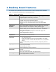
1 Desktop Board Features This chapter briefly describes the main features of Intel® Desktop Board D510MO. Table 1 summarizes the features of the Desktop Board. Table 1. Feature Summary Form Factor Processor Main Memory Chipset Integrated Graphics Audio Expansion Capabilities Peripheral Interfaces Legacy I/O Control Hardware Monitor Subsystem LAN Support Mini-ITX ([170 millimeters [6.7 inches] x 170 millimeters [6.
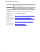
Intel Desktop Board D510MO Product Guide BIOS Instantly Available PC Technology • Intel® BIOS • Support for Advanced Configuration and Power Interface (ACPI), Plug and Play, and SMBIOS • Support for PCI Local Bus Specification, Revision 2.
Desktop Board Features Desktop Board Components Figure 1 shows the location of the major components on Intel Desktop Board D510MO. Figure 1.
Intel Desktop Board D510MO Product Guide Table 2.
Desktop Board Features Processor Intel Desktop Board D510MO includes a passively-cooled, dual-core Intel Atom processor with integrated graphics and memory controller. The processor is soldered to the Desktop Board and is not customer upgradeable. NOTE The board is designed to be passively cooled in a properly ventilated chassis. Chassis venting locations are recommended above the processor heatsink area for maximum heat dissipation effectiveness.
Intel Desktop Board D510MO Product Guide Integrated Graphics Subsystem The integrated Intel GMA 3150 graphics controller features the following: • • • • • 400 MHz core frequency High quality texture engine ⎯ DX9.0c* and OpenGL* 1.4 compliant ⎯ Hardware Pixel Shader 2.0 ⎯ Vertex Shader Model 2.0 3D Graphics Rendering enhancements ⎯ 1.
Desktop Board Features The front/back panel audio connectors are configurable through the audio device drivers. Table 3 lists the supported functions of the front panel and back panel jacks. Table 3.
Intel Desktop Board D510MO Product Guide Legacy Input/Output (I/O) Controller The legacy I/O controller provides the following: • • • • • • Two serial ports (via onboard headers) One parallel port with Extended Capabilities Port (ECP) and Enhanced Parallel Port (EPP) support via an onboard headers Serial IRQ interface compatible with serialized IRQ support for PCI systems PS/2-style keyboard and mouse ports Intelligent power management, including a programmable wake up event interface PCI power management
Desktop Board Features Table 4 describes the LED states when the board is powered up and the LAN subsystem is operating. Table 4. LAN Status LEDs LED LED Color LED State Indicates Activity (A) Green Blinking LAN activity is occurring. N/A Off 10 Mbits/s data rate is selected. Green On 100 Mbits/s data rate is selected. Yellow On 1000 Mbits/s data rate is selected. Speed (B) USB 2.0 Support The Desktop Board supports up to seven USB 2.
Intel Desktop Board D510MO Product Guide BIOS The BIOS provides the Power-On Self-Test (POST), the BIOS Setup program, the PCI and IDE auto-configuration utilities, and the video BIOS. PCI/PCI Express Auto Configuration If you install a PCI/PCI Express add-in card in your computer, the PCI/PCI Express auto-configuration utility in the BIOS automatically detects and configures the resources (IRQs, DMA channels, and I/O space) for that add-in card.
Desktop Board Features Power Management Features Power management is implemented at several levels, including: • • Software support through the Advanced Configuration and Power Interface (ACPI) Hardware support: ― Power connector ― Fan header ― +5 V standby power indicator LED ― LAN Wake capabilities ― Instantly Available PC technology ― Wake from USB ― Wake from PS/2 devices ― PME# wakeup support ― WAKE# signal wakeup support ― Wake from serial port ACPI ACPI gives the operating system direct control ov
Intel Desktop Board D510MO Product Guide Figure 4. Location of the Standby Power Indicator For more information on standby current requirements for the Desktop Board, refer to the Technical Product Specification on the Intel Desktop D510MO web page at http://www.intel.com/products/motherboard/D510MO/index.htm. Instantly Available PC Technology Instantly Available PC technology enables the board to enter the ACPI S3 (Suspend-toRAM) sleep-state.
Desktop Board Features LAN Wake Capabilities The board’s LAN wake capabilities enable remote wake-up of the computer through a network. The LAN subsystem network adapter monitors network traffic at the Media Independent Interface. The board supports LAN wake capabilities with ACPI in the following ways: • • By Ping By Magic Packet Upon detecting the configured wake packet type, the LAN subsystem asserts a wakeup signal that powers up the computer.
Intel Desktop Board D510MO Product Guide ENERGY STAR*, e-Standby, and ErP Compliance Intel Desktop Board D510MO meets the ENERGY STAR requirements listed in Table 5 when used in corresponding system configurations. Table 5. ENERGY STAR Requirements ENERGY STAR Specification Computer Type v4.0 Desktop Computer v4.
2 Installing and Replacing Desktop Board Components This chapter tells you how to: • • • • • • • • • • • Install the I/O shield Install and remove the Desktop Board Install and remove system memory Connect SATA drives Install a Wireless LAN card Install an Intel Z-U130 USB Solid-State Drive (or compatible device) Connect to internal headers Connect chassis fan and power supply cables Set the BIOS configuration jumper Clear passwords Replace the battery Before You Begin CAUTION The procedures in this chapt
Intel Desktop Board D510MO Product Guide CAUTION Failure to ensure appropriate airflow may result in reduced performance of both the processor and/or voltage regulator or, in some instances, damage to the board. All responsibility for determining the adequacy of any thermal or system design remains solely with the reader. Intel makes no warranties or representations that merely following the instructions presented in this document will result in a system with adequate thermal performance.
Installing and Replacing Desktop Board Components Installation Precautions When you install and test the Intel Desktop Board, observe all warnings and cautions in the installation instructions.
Intel Desktop Board D510MO Product Guide Installing the I/O Shield The Desktop Board comes with an I/O shield. When installed in the chassis, the shield blocks radio frequency transmissions, protects internal components from dust and foreign objects, and promotes correct airflow within the chassis. Install the I/O shield before installing the Desktop Board in the chassis. Place the shield inside the chassis as shown in Figure 5. Press the shield into place so that it fits tightly and securely.
Installing and Replacing Desktop Board Components Installing and Removing the Desktop Board CAUTION Only qualified technical personnel should do this procedure. Disconnect the computer from its power source before performing the procedures described here. Failure to disconnect the power before you open the computer can result in personal injury or equipment damage. Refer to your chassis manual for instructions on installing and removing the Desktop Board.
Intel Desktop Board D510MO Product Guide Installing DIMMs To make sure you have the correct DIMM, place it on the illustration in Figure 7 showing the DDR2 DIMM. All the notches should match the DDR2 DIMM. Figure 7.
Installing and Replacing Desktop Board Components 1. Observe the precautions in "Before You Begin" on page 23. 2. Turn off all peripheral devices connected to the computer. Turn off the computer and disconnect the AC power cord. 3. Remove the computer’s cover and locate the DIMM socket (see Figure 8). Figure 8. Installing a DIMM 4. Make sure the clips at either end of the DIMM socket are pushed outward to the open position. 5. Position the DIMM above the socket.
Intel Desktop Board D510MO Product Guide Removing DIMMs To remove a DIMM, follow these steps: 1. 2. 3. 4. 5. Observe the precautions in "Before You Begin" on page 23. Turn off all peripheral devices connected to the computer. Turn off the computer. Remove the AC power cord from the computer. Remove the computer’s cover. Gently spread the retaining clips at each end of the DIMM socket. The DIMM pops out of the socket. 6.
Installing and Replacing Desktop Board Components Figure 9.
Intel Desktop Board D510MO Product Guide Installing a Wireless LAN Card in the PCI Express Full-Mini Card Slot A wireless LAN card can be installed in the Desktop Board’s PCI Express Full-Mini Card slot. To install a wireless LAN card on the Desktop Board, see Figure 10 and follow these steps: 1. Observe the precautions in "Before You Begin" on page 23. 2. Locate the PCI Express Full-Mini Card slot. 3.
Installing and Replacing Desktop Board Components Installing an Intel® Z-U130 USB Solid-State Drive (or Compatible Device) An Intel Z-U130 USB Solid-State Drive (or compatible device) can be installed on the Desktop Board by using the onboard USB 2.0 header indicated in Figure 1, DD. This header provides support for the solid state drive. To install an Intel Z-U130 USB Solid-State Drive (or compatible device) on the Desktop Board, follow these steps: 1.
Intel Desktop Board D510MO Product Guide Connecting to the Internal Headers Before connecting cables to the internal headers, observe the precautions in "Before You Begin" on page 23. Figure 12 shows the location of the board’s internal headers. Figure 12.
Installing and Replacing Desktop Board Components Connecting the Front Panel Audio Header Figure 12, A shows the location of the front panel audio header. The front panel audio header can be used for both Intel HD Audio and AC ‘97 Audio. Table 6 shows the pin assignments for the Intel HD Audio and Table 7 shows the pin assignments for AC ‘97 Audio. Table 6.
Intel Desktop Board D510MO Product Guide Connecting to the S/PDIF Header Before connecting to the S/PDIF connector, observe the precautions in "Before You Begin" on page 23. See Figure 12, B on page 34 for the location of the S/PDIF header. Table 8 shows the pin assignments for the S/PDIF header. Table 8. S/PDIF Header Pin Signal Name 1 Ground 2 S/PDIF out 3 VCC (5V) Connecting to the Serial Headers Before connecting to the serial headers, observe the precautions in "Before You Begin" on page 23.
Installing and Replacing Desktop Board Components Pin Standard Signal Name ECP Signal Name EPP Signal Name 9 PD3 PD3 PD3 10 GROUND GROUND GROUND 11 PD4 PD4 PD4 12 GROUND GROUND GROUND 13 PD5 PD5 PD5 14 GROUND GROUND GROUND 15 PD6 PD6 PD6 16 GROUND GROUND GROUND 17 PD7 PD7 PD7 18 GROUND GROUND GROUND 19 ACK# ACK# INTR 20 GROUND GROUND GROUND 21 BUSY BUSY#, PERIPHACK WAIT# 22 GROUND GROUND GROUND 23 PERROR PE, ACKREVERSE# PE 24 GROUND GROUND
Intel Desktop Board D510MO Product Guide Connecting to the Front Panel Header Before connecting to the front panel header, observe the precautions in "Before You Begin" on page 23. See Figure 12, F on page 34 for the location of the front panel header. Table 12 shows the pin assignments for the front panel header. Table 12.
Installing and Replacing Desktop Board Components Table 14. Front Panel USB Header with Intel Z-U130 USB Solid-State Drive (or Compatible Device) Support Pin Signal Name Pin Signal Name 1 +5 VDC 2 No Connect 3 D- 4 No Connect 5 D+ 6 No Connect 7 Ground 8 No Connect 9 KEY (no pin) 10 LED# Connecting a Chassis Fan Figure 13 shows the location of the chassis fan header. Connect the chassis fan cable to this header. Figure 13.
Intel Desktop Board D510MO Product Guide Connecting the Power Supply Cable CAUTION Failure to use an appropriate power supply to the Desktop Board may result in damage to the board or the system may not function properly. Figure 14 shows the location of the power connector. Figure 14. Connecting a Power Supply Cable 1. Observe the precautions in "Before You Begin" on page 23. 2. Connect the main power supply cable (2 x 12) to the 2 x 12 connector (Figure 14).
Installing and Replacing Desktop Board Components Setting the BIOS Configuration Jumper NOTE Always turn off the power and unplug the power cord from the computer before changing a jumper. Moving the jumper with the power on may result in unreliable computer operation. Figure 15 shows the location of the Desktop Board’s BIOS configuration jumper block. Figure 15. BIOS Configuration Jumper Block The three-pin BIOS jumper block enables board operating modes.
Intel Desktop Board D510MO Product Guide Figure 15 shows the location of the Desktop Board’s BIOS configuration jumper block. Table 15. Jumper Settings for the BIOS Setup Program Modes Jumper Setting Mode Description Normal (default) (1-2) The BIOS uses the current configuration and passwords for booting. Configure (2-3) After the Power-On Self-Test (POST) runs, the BIOS displays the Maintenance Menu. Use this menu to clear passwords.
Installing and Replacing Desktop Board Components 10. Turn off the computer. Disconnect the computer’s power cord from the AC power source. 11. Remove the computer cover. 12. To restore normal operation, place the jumper on pins 1-2 as shown below. 13. Replace the cover, plug in the computer, and turn on the computer. Replacing the Battery A coin-cell battery powers the Desktop Board’s real-time clock and CMOS memory.
Intel Desktop Board D510MO Product Guide VARO Räjähdysvaara, jos pariston tyyppi on väärä. Paristot on kierrätettävä, jos se on mahdollista. Käytetyt paristot on hävitettävä paikallisten ympäristömääräysten mukaisesti. VORSICHT Bei falschem Einsetzen einer neuen Batterie besteht Explosionsgefahr. Die Batterie darf nur durch denselben oder einen entsprechenden, vom Hersteller empfohlenen Batterietyp ersetzt werden. Entsorgen Sie verbrauchte Batterien den Anweisungen des Herstellers entsprechend.
Installing and Replacing Desktop Board Components VIGYÁZAT Ha a telepet nem a megfelelő típusú telepre cseréli, az felrobbanhat. A telepeket lehetőség szerint újra kell hasznosítani. A használt telepeket a helyi környezetvédelmi előírásoknak megfelelően kell kiselejtezni. AWAS Risiko letupan wujud jika bateri digantikan dengan jenis yang tidak betul. Bateri sepatutnya dikitar semula jika boleh. Pelupusan bateri terpakai mestilah mematuhi peraturan alam sekitar tempatan.
Intel Desktop Board D510MO Product Guide OСТОРОГА Використовуйте батареї правильного типу, інакше існуватиме ризик вибуху. Якщо можливо, використані батареї слід утилізувати. Утилізація використаних батарей має бути виконана згідно місцевих норм, що регулюють охорону довкілля.
Installing and Replacing Desktop Board Components 1. Observe the precautions in "Before You Begin" (see page 23). 2. Turn off all peripheral devices connected to the computer. Disconnect the computer’s power cord from the AC power source (wall outlet or power adapter). 3. Remove the computer cover. 4. Locate the battery on the board (see Figure 16). 5. Push the battery retention clip aside and remove the battery from the connector as shown in Figure 16.
Intel Desktop Board D510MO Product Guide 48
3 Updating the BIOS The BIOS Setup program can be used to view and change the BIOS settings for the computer. You can access the BIOS Setup program by pressing the key after the Power-On Self-Test (POST) memory test begins and before the operating system boot begins. This chapter tells you how to update the BIOS by either using the Intel Express BIOS Update utility or the Iflash Memory Update utility, and how to recover the BIOS if an update fails.
Intel Desktop Board D510MO Product Guide Updating the BIOS with the Iflash Memory Update Utility You can use the information in this section to update the BIOS using the Iflash Memory Update Utility. Obtaining the BIOS Update File You can update to a new version of the BIOS by using the Iflash BIOS update file. The Iflash BIOS update file is a compressed file that contains the files you need to update the BIOS.
Updating the BIOS Recovering the BIOS It is unlikely that anything will interrupt a BIOS update; however, if an interruption occurs, the BIOS could be damaged. Table 16 lists the drives and media types that can and cannot be used for BIOS recovery. The BIOS recovery media does not have to be bootable. Table 16.
Intel Desktop Board D510MO Product Guide 52
A Board Status and Error Messages This appendix describes status and error messages generated by the Desktop Board’s BIOS. The BIOS indicates these error messages with front-panel Power LED blink codes, speaker beep codes, and by displaying text on the video monitor. BIOS Beep Codes The BIOS uses audible beep codes to signal status messages and error messages indicating recoverable errors that occur during the POST. The beep codes are listed in Table 17.
Intel Desktop Board D510MO Product Guide BIOS Front-panel Power LED Blink Codes The BIOS also blinks the front-panel power LED to signal status messages and error messages indicating certain recoverable errors that occur during the POST. The blink codes are listed in Table 18. Table 18. BIOS Front-panel Power LED Blink Codes Type Pattern Note BIOS update in progress Off when the update begins, then on for 0.5 second, and then off for 0.5 second. The pattern repeats until the BIOS update is complete.
B Regulatory Compliance This appendix contains the following regulatory compliance information for Intel Desktop Board D510MO: • • • • • Safety standards European Union Declaration of Conformity statement Product Ecology statements Electromagnetic Compatibility (EMC) regulations Product certifications Safety Standards Intel Desktop Board D510MO complies with the safety standards stated in Table 20 when correctly installed in a compatible host system. Table 20.
Intel Desktop Board D510MO Product Guide European Union Declaration of Conformity Statement We, Intel Corporation, declare under our sole responsibility that the product Intel® Desktop Board D510MO is in conformity with all applicable essential requirements necessary for CE marking, following the provisions of the European Council Directives 2004/108/EC (EMC Directive) and 2006/95/EC (Low Voltage Directive).
Regulatory Compliance Norsk Dette produktet er i henhold til bestemmelsene i det europeiske direktivet 2004/108/EC & 2006/95/EC. Polski Niniejszy produkt jest zgodny z postanowieniami Dyrektyw Unii Europejskiej 2004/108/EC i 2006/95/EC. Portuguese Este produto cumpre com as normas da Diretiva Européia 2004/108/EC & 2006/95/EC. Español Este producto cumple con las normas del Directivo Europeo 2004/108/EC & 2006/95/EC.
Intel Desktop Board D510MO Product Guide Deutsch Als Teil von Intels Engagement für den Umweltschutz hat das Unternehmen das Intel Produkt-Recyclingprogramm implementiert, das Einzelhandelskunden von Intel Markenprodukten ermöglicht, gebrauchte Produkte an ausgewählte Standorte für ordnungsgemäßes Recycling zurückzugeben. Details zu diesem Programm, einschließlich der darin eingeschlossenen Produkte, verfügbaren Standorte, Versandanweisungen, Bedingungen usw., finden Sie auf der http://www.intel.
Regulatory Compliance Portuguese Como parte deste compromisso com o respeito ao ambiente, a Intel implementou o Programa de Reciclagem de Produtos para que os consumidores finais possam enviar produtos Intel usados para locais selecionados, onde esses produtos são reciclados de maneira adequada. Consulte o site http://www.intel.
Intel Desktop Board D510MO Product Guide Lead-free 2LI/Pb-free 2LI Board The electronics industry is transitioning to European Union (EU) Restriction of Hazardous Substances (RoHS)-compliant products. The RoHS legislation restricts the use of six materials. One of these restricted materials is lead. Lead is the most common and problematic of the RoHS restricted materials. There are exemptions in RoHS that allow the use of lead in some very limited locations in electronic products.
Regulatory Compliance Restriction of Hazardous Substances (RoHS) European Union RoHS EU RoHS Directive 2002/95/EC restricts the use of the following six materials in various types of electronic and electrical equipment: • • • • • • Lead Mercury Cadmium Hexavalent chromium Polybrominated biphenyls (PBB) Polybrominated diphenyl ether (PBDE) The maximum concentrations allowed are 0.1% or 1000 ppm (except for cadmium, which is limited to 0.01% or 100 ppm) by weight of homogeneous material.
Intel Desktop Board D510MO Product Guide The China MII also stipulates that a material Self Declaration Table (SDT) must be included in a product’s user documentation. The SDT for Intel Desktop Board D510MO is shown in Figure 17. Figure 17.
Regulatory Compliance EMC Regulations Intel Desktop Board D510MO complies with the EMC regulations stated in Table 23 when correctly installed in a compatible host system. Table 23. EMC Regulations Regulation (Class B) Title FCC 47 CFR Part 15, Subpart B Title 47 of the Code of Federal Regulations, Part 15, Subpart B, Radio Frequency Devices. (USA) ICES-003 Issue 4 Interference-Causing Equipment Standard, Digital Apparatus.
Intel Desktop Board D510MO Product Guide Korean Class B statement translation: This is household equipment that is certified to comply with EMC requirements. You may use this equipment in residential environments and other non-residential environments. Ensure Electromagnetic Compatibility (EMC) Compliance Before computer integration, make sure that the power supply and other modules or peripherals, as applicable, have passed Class B EMC testing and are marked accordingly.
Regulatory Compliance Product Certifications Board-Level Certification Markings Intel Desktop Board D510MO has the product certification markings shown in Table 24. Table 24. Product Certification Markings Description UL joint US/Canada Recognized Component mark. Includes adjacent UL file number for Intel Desktop Boards: E210882. Mark FCC Declaration of Conformity logo mark for Class B equipment. Includes Intel name and D510MO model designation. CE mark.
Intel Desktop Board D510MO Product Guide Chassis and Component Certifications Ensure that the chassis and certain components; such as the power supply, peripheral drives, wiring, and cables; are components certified for the country or market where used. Agency certification marks on the product are proof of certification. Typical product certifications include: In Europe The CE marking signifies compliance with all applicable European requirements.