Intel® Desktop Board D425KT Product Guide Order Number: E95572-001
Revision History Revision -001 Revision History First release of the Intel® Desktop Board D425KT Product Guide Date June 2010 Disclaimer Information in this document is provided in connection with Intel® products. No license, express or implied, by estoppel or otherwise, to any intellectual property rights is granted by this document.
Preface This Product Guide gives information about board layout, component installation, and regulatory requirements for Intel® Desktop Board D425KT. Intended Audience The Product Guide is intended for technically qualified personnel. It is not intended for general audiences. Intended Uses All Intel® Desktop Boards are evaluated as Information Technology Equipment (I.T.E.) for use in personal computers (PC) for installation in homes, offices, schools, computer rooms, and similar locations.
Intel Desktop Board D425KT Product Guide Terminology The table below gives descriptions to some common terms used in the product guide.
Contents 1 Desktop Board Features Desktop Board Components.................................................................................11 Processor..........................................................................................................13 System Memory.................................................................................................13 Integrated Graphics Subsystem ...........................................................................14 Intel® NM10 Express Chipset ...
Intel Desktop Board D425KT Product Guide A Board Status and Error Messages BIOS Beep Codes ...............................................................................................47 BIOS Front-panel Power LED Blink Codes ..............................................................48 POST Error Messages..........................................................................................48 B Regulatory Compliance Safety Standards ................................................................
Contents Figures 1. 2. 3. 4. 5. 6. 7. 8. 9. 10. 11. 12. 13. 14. Intel Desktop Board D425KT Components ........................................................11 Back Panel Audio Connectors .........................................................................15 LAN Status LEDs ..........................................................................................16 Location of the Standby Power Indicator ..........................................................19 Installing the I/O Shield .........
Intel Desktop Board D425KT Product Guide viii
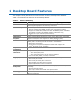
1 Desktop Board Features This chapter briefly describes the main features of Intel® Desktop Board D425KT. Table 1 summarizes the features of the Desktop Board. Table 1. Feature Summary Form Factor Processor Main Memory Chipset Integrated Graphics Audio Expansion Capabilities Peripheral Interfaces Legacy I/O Control Hardware Monitor Subsystem LAN Support Mini-ITX ([170 millimeters [6.7 inches] x 170 millimeters [6.
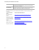
Intel Desktop Board D425KT Product Guide BIOS Instantly Available PC Technology • Intel® BIOS • Support for Advanced Configuration and Power Interface (ACPI), Plug and Play, and SMBIOS • Support for PCI Local Bus Specification, Revision 2.
Desktop Board Features Desktop Board Components Figure 1 shows the location of the major components on Intel Desktop Board D425KT. Figure 1.
Intel Desktop Board D425KT Product Guide Table 2.
Desktop Board Features Processor Intel Desktop Board D425KT includes a passively-cooled, single-core Intel Atom processor with integrated graphics and memory controller. The processor is soldered to the Desktop Board and is not customer upgradeable. NOTE The board is designed to be passively cooled in a properly ventilated chassis. Chassis venting locations are recommended above the processor heatsink area for maximum heat dissipation effectiveness.
Intel Desktop Board D425KT Product Guide Integrated Graphics Subsystem The integrated Intel GMA 3150 graphics controller features the following: • • • • • 400 MHz core frequency High quality texture engine ⎯ DX9.0c* and OpenGL* 1.4 compliant ⎯ Hardware Pixel Shader 2.0 ⎯ Vertex Shader Model 2.0 3D Graphics Rendering enhancements ⎯ 1.
Desktop Board Features The front/back panel audio connectors are configurable through the audio device drivers. Table 3 lists the supported functions of the front panel and back panel jacks. Table 3.
Intel Desktop Board D425KT Product Guide LAN Subsystem The LAN subsystem consists of the following: • • • Intel NM10 Express Chipset Realtek 8105E Ethernet Controller for 10/100 Mbits/s Ethernet LAN connectivity RJ-45 LAN connector with integrated status LEDs Additional features of the LAN subsystem include: • • • CSMA/CD protocol engine LAN connect interface that supports the ethernet controller PCI bus power management ⎯ Supports ACPI technology ⎯ Supports LAN wake capabilities LAN drivers are availa
Desktop Board Features USB 2.0 Support The Desktop Board supports up to eight USB 2.0 ports (four ports routed to the back panel and four ports routed to two front panel USB 2.0 headers). The USB 2.0 ports are compatible with USB 1.1 devices. USB 1.1 devices will function normally at USB 1.1 speeds. USB 2.0 support requires both an operating system and drivers that fully support USB 2.0 transfer rates. Disabling High-Speed USB in the BIOS reverts all USB 2.0 ports to USB 1.1 operation.
Intel Desktop Board D425KT Product Guide Security Passwords The BIOS includes security features that restrict whether the BIOS Setup program can be accessed and who can boot the computer. A supervisor password and a user password can be set for the BIOS Setup and for booting the computer, with the following restrictions: • • • The supervisor password gives unrestricted access to view and change all Setup options.
Desktop Board Features +5 V Standby Power Indicator CAUTION If the AC power has been switched off and the standby power indicator is still lit, disconnect the power cord before installing or removing any devices connected to the board. Failure to do so could damage the board and any attached devices. The Desktop Board’s standby power indicator, shown in Figure 4, is lit when there is standby power to the system.
Intel Desktop Board D425KT Product Guide Instantly Available PC Technology Instantly Available PC technology enables the board to enter the ACPI S3 (Suspend-toRAM) sleep-state. While in the ACPI S3 sleep-state, the computer will appear to be off (the hard drive(s) and fan will power off, the front panel power LED will blink). When signaled by a wake-up device or event, the system quickly returns to its last known state. The board supports the PCI Bus Power Management Interface Specification.
Desktop Board Features Battery A coin-cell battery on the Desktop Board keeps the values in CMOS RAM and the clock current when the computer is turned off. Go to page 37 for instructions on how to replace the battery. Real-Time Clock The Desktop Board includes a time-of-day clock and a 100-year calendar. The coincell battery keeps the clock current when the computer is turned off.
Intel Desktop Board D425KT Product Guide 22
2 Installing and Replacing Desktop Board Components This chapter tells you how to: • • • • • • • • • Install the I/O shield Install and remove the Desktop Board Install and remove system memory Connect SATA drives Connect to internal headers Connect chassis fan and power supply cables Set the BIOS configuration jumper Clear passwords Replace the battery Before You Begin CAUTION The procedures in this chapter assume familiarity with the general terminology associated with personal computers and with the sa
Intel Desktop Board D425KT Product Guide CAUTION Failure to ensure appropriate airflow may result in reduced performance of both the processor and/or voltage regulator or, in some instances, damage to the board. All responsibility for determining the adequacy of any thermal or system design remains solely with the reader. Intel makes no warranties or representations that merely following the instructions presented in this document will result in a system with adequate thermal performance.
Installing and Replacing Desktop Board Components Installation Precautions When you install and test the Intel Desktop Board, observe all warnings and cautions in the installation instructions.
Intel Desktop Board D425KT Product Guide Installing the I/O Shield The Desktop Board comes with an I/O shield. When installed in the chassis, the shield blocks radio frequency transmissions, protects internal components from dust and foreign objects, and promotes correct airflow within the chassis. Install the I/O shield before installing the Desktop Board in the chassis. Place the shield inside the chassis as shown in Figure 5. Press the shield into place so that it fits tightly and securely.
Installing and Replacing Desktop Board Components Installing and Removing the Desktop Board CAUTION Only qualified technical personnel should do this procedure. Disconnect the computer from its power source before performing the procedures described here. Failure to disconnect the power before you open the computer can result in personal injury or equipment damage. Refer to your chassis manual for instructions on installing and removing the Desktop Board.
Intel Desktop Board D425KT Product Guide Installing and Removing Memory NOTE To be fully compliant with all applicable Intel SDRAM memory specifications, the boards require DIMMs that support the Serial Presence Detect (SPD) data structure. The Desktop Board has two 204-pin DDR3 SO-DIMM sockets that support up to 4 GB of system memory. To install system memory on the Desktop Board, see Figure 7 and follow these steps: 1. Observe the precautions in "Before You Begin" on page 23. 2.
Installing and Replacing Desktop Board Components Connecting SATA Drives The board has two SATA connectors each supporting one SATA drive. The included SATA cables support the Serial ATA protocol. For correct cable and drive function: 1. Observe the precautions in "Before You Begin" on page 23. 2. Attach one end of the cable to the connector on the board (Figure 8, A) and connect the other end to the drive (Figure 8, B). Figure 8.
Intel Desktop Board D425KT Product Guide Connecting to the Internal Headers Before connecting cables to the internal headers, observe the precautions in "Before You Begin" on page 23. Figure 9 shows the location of the board’s internal headers. Figure 9.
Installing and Replacing Desktop Board Components Connecting to the Front Panel Audio Header Figure 9, A shows the location of the front panel audio header. The front panel audio header can be used for both Intel HD Audio and AC ‘97 Audio. Table 5 shows the pin assignments for the Intel HD Audio and Table 6 shows the pin assignments for AC ‘97 Audio. Table 5.
Intel Desktop Board D425KT Product Guide Connecting to the Front Panel Header Before connecting to the front panel header, observe the precautions in "Before You Begin" on page 23. See Figure 9, C on page 30 for the location of the front panel header. Table 8 shows the pin assignments for the front panel header. Table 8.
Installing and Replacing Desktop Board Components Connecting a Chassis Fan Figure 10 shows the location of the chassis fan header. Connect the chassis fan cable to this header. Figure 10.
Intel Desktop Board D425KT Product Guide Connecting a Power Supply CAUTION Failure to connect an appropriate power supply to the Desktop Board may result in damage to the board or the system may not function properly. Figure 11 shows the location of the power connectors. Figure 11. Connecting Power Supply Cables 1. Observe the precautions in "Before You Begin" on page 23. 2. Connect the main power supply cable to the 2 x 12 pin connector (Figure 11, B). 3.
Installing and Replacing Desktop Board Components Setting the BIOS Configuration Jumper NOTE Always turn off the power and unplug the power cord from the computer before changing a jumper. Moving the jumper with the power on may result in unreliable computer operation. Figure 12 shows the location of the Desktop Board’s BIOS configuration jumper block. Figure 12. BIOS Configuration Jumper Block The three-pin BIOS configuration jumper block enables board operating modes.
Intel Desktop Board D425KT Product Guide Figure 12 shows the location of the Desktop Board’s BIOS configuration jumper block. Table 10. Jumper Settings for the BIOS Setup Program Modes Jumper Setting Mode Description Normal (default) (1-2) The BIOS uses the current configuration and passwords for booting. Configure (2-3) After the Power-On Self-Test (POST) runs, the BIOS displays the Maintenance Menu. Use this menu to clear passwords.
Installing and Replacing Desktop Board Components 12. To restore normal operation, place the jumper on pins 1-2 as shown below. 13. Replace the cover, plug in the computer, and turn on the computer. Replacing the Battery A coin-cell battery powers the Desktop Board’s real-time clock and CMOS memory. When the computer is not plugged into a wall socket, the battery has an estimated life of three years.
Intel Desktop Board D425KT Product Guide VORSICHT Bei falschem Einsetzen einer neuen Batterie besteht Explosionsgefahr. Die Batterie darf nur durch denselben oder einen entsprechenden, vom Hersteller empfohlenen Batterietyp ersetzt werden. Entsorgen Sie verbrauchte Batterien den Anweisungen des Herstellers entsprechend. AVVERTIMENTO Esiste il pericolo di un esplosione se la pila non viene sostituita in modo corretto. Utilizzare solo pile uguali o di tipo equivalente a quelle consigliate dal produttore.
Installing and Replacing Desktop Board Components VIGYÁZAT Ha a telepet nem a megfelelő típusú telepre cseréli, az felrobbanhat. A telepeket lehetőség szerint újra kell hasznosítani. A használt telepeket a helyi környezetvédelmi előírásoknak megfelelően kell kiselejtezni. AWAS Risiko letupan wujud jika bateri digantikan dengan jenis yang tidak betul. Bateri sepatutnya dikitar semula jika boleh. Pelupusan bateri terpakai mestilah mematuhi peraturan alam sekitar tempatan.
Intel Desktop Board D425KT Product Guide UYARI Yanlış türde pil takıldığında patlama riski vardır. Piller mümkün olduğunda geri dönüştürülmelidir. Kullanılmış piller, yerel çevre yasalarına uygun olarak atılmalıdır. OСТОРОГА Використовуйте батареї правильного типу, інакше існуватиме ризик вибуху. Якщо можливо, використані батареї слід утилізувати. Утилізація використаних батарей має бути виконана згідно місцевих норм, що регулюють охорону довкілля.
Installing and Replacing Desktop Board Components 1. Observe the precautions in "Before You Begin" (see page 23). 2. Turn off all peripheral devices connected to the computer. Disconnect the computer’s power cord from the AC power source (wall outlet or power adapter). 3. Remove the computer cover. 4. Locate the battery on the board (see Figure 13). 5. Push the battery retention clip aside and remove the battery from the connector as shown in Figure 13.
Intel Desktop Board D425KT Product Guide 42
3 Updating the BIOS The BIOS Setup program can be used to view and change the BIOS settings for the computer. You can access the BIOS Setup program by pressing the key after the Power-On Self-Test (POST) memory test begins and before the operating system boot begins. This chapter tells you how to update the BIOS by either using the Intel Express BIOS Update utility or the Iflash Memory Update utility, and how to recover the BIOS if an update fails.
Intel Desktop Board D425KT Product Guide Updating the BIOS with the Iflash Memory Update Utility You can use the information in this section to update the BIOS using the Iflash Memory Update Utility. Obtaining the BIOS Update File You can update to a new version of the BIOS by using the Iflash BIOS update file. The Iflash BIOS update file is a compressed file that contains the files you need to update the BIOS.
Updating the BIOS Recovering the BIOS It is unlikely that anything will interrupt a BIOS update; however, if an interruption occurs, the BIOS could be damaged. Table 11 lists the drives and media types that can and cannot be used for BIOS recovery. The BIOS recovery media does not have to be bootable. Table 11.
Intel Desktop Board D425KT Product Guide 46
A Board Status and Error Messages This appendix describes status and error messages generated by the Desktop Board’s BIOS. The BIOS indicates these error messages with front-panel Power LED blink codes, speaker beep codes, and by displaying text on the video monitor. BIOS Beep Codes The BIOS uses audible beep codes to signal status messages and error messages indicating recoverable errors that occur during the POST. The beep codes are listed in Table 12.
Intel Desktop Board D425KT Product Guide BIOS Front-panel Power LED Blink Codes The BIOS also blinks the front-panel power LED to signal status messages and error messages indicating certain recoverable errors that occur during the POST. The blink codes are listed in Table 13. Table 13. BIOS Front-panel Power LED Blink Codes Type Pattern Note BIOS update in progress Off when the update begins, then on for 0.5 second, and then off for 0.5 second. The pattern repeats until the BIOS update is complete.
B Regulatory Compliance This appendix contains the following regulatory compliance information for Intel Desktop Board D425KT: • • • • • Safety standards European Union Declaration of Conformity statement Product Ecology statements Electromagnetic Compatibility (EMC) regulations Product certifications Safety Standards Intel Desktop Board D425KT complies with the safety standards stated in Table 15 when correctly installed in a compatible host system. Table 15.
Intel Desktop Board D425KT Product Guide European Union Declaration of Conformity Statement We, Intel Corporation, declare under our sole responsibility that the product Intel® Desktop Board D425KT is in conformity with all applicable essential requirements necessary for CE marking, following the provisions of the European Council Directives 2004/108/EC (EMC Directive), 2006/95/EC (Low Voltage Directive), and 2002/95/EC (ROHS Directive).
Regulatory Compliance Portuguese Este produto cumpre com as normas da Diretiva Européia 2004/108/EC, 2006/95/EC & 2002/95/EC. Español Este producto cumple con las normas del Directivo Europeo 2004/108/EC, 2006/95/EC & 2002/95/EC. Slovensky Tento produkt je v súlade s ustanoveniami európskych direktív 2004/108/EC, 2006/95/EC a 2002/95/EC. Slovenščina Izdelek je skladen z določbami evropskih direktiv 2004/108/EC, 2006/95/EC in 2002/95/EC.
Intel Desktop Board D425KT Product Guide Deutsch Als Teil von Intels Engagement für den Umweltschutz hat das Unternehmen das Intel Produkt-Recyclingprogramm implementiert, das Einzelhandelskunden von Intel Markenprodukten ermöglicht, gebrauchte Produkte an ausgewählte Standorte für ordnungsgemäßes Recycling zurückzugeben. Details zu diesem Programm, einschließlich der darin eingeschlossenen Produkte, verfügbaren Standorte, Versandanweisungen, Bedingungen usw., finden Sie auf der http://intel.
Regulatory Compliance Portuguese Como parte deste compromisso com o respeito ao ambiente, a Intel implementou o Programa de Reciclagem de Produtos para que os consumidores finais possam enviar produtos Intel usados para locais selecionados, onde esses produtos são reciclados de maneira adequada. Consulte o site http://intel.
Intel Desktop Board D425KT Product Guide China RoHS Intel Desktop Board D425KT is a China RoHS-compliant product. The China Ministry of Information Industry (MII) stipulates that a material Self Declaration Table (SDT) must be included in a product’s user documentation. The SDT for Intel Desktop Board D425KT is shown in Figure 14. Figure 14.
Regulatory Compliance EMC Regulations Intel Desktop Board D425KT complies with the EMC regulations stated in Table 16 when correctly installed in a compatible host system. Table 16. EMC Regulations Regulation Title FCC 47 CFR Part 15, Subpart B Title 47 of the Code of Federal Regulations, Part 15, Subpart B, Radio Frequency Devices. (USA) ICES-003 Interference-Causing Equipment Standard, Digital Apparatus.
Intel Desktop Board D425KT Product Guide and on, the user is encouraged to try to correct the interference by one or more of the following measures: • • • • Reorient or relocate the receiving antenna. Increase the separation between the equipment and the receiver. Connect the equipment to an outlet on a circuit other than the one to which the receiver is connected. Consult the dealer or an experienced radio/TV technician for help.
Regulatory Compliance Korea Class B Statement Korea Class B Statement translation: This equipment is for home use, and has acquired electromagnetic conformity registration, so it can be used not only in residential areas, but also other areas. Ensure Electromagnetic Compatibility (EMC) Compliance Before computer integration, make sure that the power supply and other modules or peripherals, as applicable, have passed Class B EMC testing and are marked accordingly.
Intel Desktop Board D425KT Product Guide Product Certifications Board-Level Certifications Intel Desktop Board D425KT has the regulatory compliance marks shown in Table 17. Table 17. Regulatory Compliance Marks Description Mark UL joint US/Canada Recognized Component mark. Includes adjacent UL file number for Intel Desktop Boards: E210882. FCC Declaration of Conformity logo mark for Class B equipment. CE mark.
Regulatory Compliance Chassis- and Component-Level Certifications Ensure that the chassis and certain components; such as the power supply, peripheral drives, wiring, and cables; are components certified for the country or market where used. Agency certification marks on the product are proof of certification. Typical product certifications include: In Europe The CE mark indicates compliance with all applicable European requirements.
Intel Desktop Board D425KT Product Guide ENERGY STAR*, e-Standby, and ErP Compliance Intel Desktop Board D425KT meets the ENERGY STAR requirements listed in Table 18 when used in corresponding system configurations. Table 18. ENERGY STAR Requirements ENERGY STAR Specification Computer Type v4.0 Desktop Computer v4.