
Nettop Platform for 2008 System Design White Paper


System Testing
White Paper 37
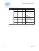
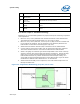
TC # Description Location [Axis]
5 MCH Tcase
(TMCH CASE)
(Type-K) Center point of MCH case top surface.
6 ICH Case
(TICH CASE)
Centered on ICH case top surface.
8 HDD
(THDD)
3mm away from component’s surface exposed to system
interior.
8 ODD
(TODD)
3mm away from component’s surface exposed to system
interior.
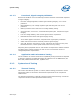
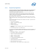
T
CASE
thermo couple 0° attachment metrology
Following is the recommended guideline for proper technique of measuring component
case temperature.
1. Mill a 3.3 mm [0.13 in] diameter hole centered on bottom of the heatsink base.
The milled hole should be approximately 1.5 mm [0.06 in] deep.
2. Mill a 1.3 mm [0.05 in] wide slot, 0.5 mm [0.02 in] deep, from the centered hole
to one edge of the heatsink. The slot should be in the direction parallel to the
heatsink fins as illustrated in following figure (top view).
3. Attach thermal interface material (TIM) to the bottom of the heatsink base.
4. Cut out portions of the TIM to make room for the thermocouple wire and bead.
The cutouts should match the slot and hole milled into the heatsink base.
5. Attach a 36 gauge or smaller K-type thermocouple bead to the center of the top
surface of the die using cement with high thermal conductivity. During this step,
make sure no contact is present between the thermocouple cement and the
heatsink base because any contact will affect the thermocouple reading. It is
critical that the thermocouple bead makes contact with the die.
Figure 15 shows
modification at bottom side of heatsink for 0° TC attachment.
6. Attach heatsink assembly to the component, and route thermocouple wires out
through the milled slot.
Figure 15 0° Angle Attach Methodology (top view, not to scale)