
Technical product specification


Table Of Contents
- Intel® NUC Board NUC5i5RYB and Intel® NUC Board NUC5i3RYB Technical Product Specification
- Revision History
- Contents
- 1 Product Description
- 1.1 Overview
- 1.2 Online Support
- 1.3 Processor
- 1.4 System Memory
- 1.5 Processor Graphics Subsystem
- 1.5.1 Integrated Graphics
- 1.5.1.1 Intel® High Definition (Intel® HD) Graphics
- 1.5.1.2 Video Memory Allocation
- 1.5.1.3 Mini High Definition Multimedia Interface* (Mini HDMI*)
- 1.5.1.4 Mini DisplayPort*
- 1.5.1.5 Multiple DisplayPort and HDMI Configurations
- 1.5.1.6 High-bandwidth Digital Content Protection (HDCP)
- 1.5.1.7 Integrated Audio Provided by the Mini HDMI and Mini DisplayPort Interfaces
- 1.5.1 Integrated Graphics
- 1.6 USB
- 1.7 SATA Interface
- 1.8 Real-Time Clock Subsystem
- 1.9 Audio Subsystem
- 1.10 LAN Subsystem
- 1.11 Hardware Management Subsystem
- 1.12 Power Management
- 2 Technical Reference
- 2.1 Memory Resources
- 2.2 Connectors and Headers
- 2.2.1 Front Panel Connectors
- 2.2.2 Back Panel Connectors
- 2.2.3 Connectors and Headers (Bottom)
- 2.3 BIOS Security Jumper
- 2.4 Mechanical Considerations
- 2.5 Electrical Considerations
- 2.6 Thermal Considerations
- 2.7 Reliability
- 2.8 Environmental
- 3 Overview of BIOS Features
- 4 Error Messages and Blink Codes
- 5 Regulatory Compliance and Battery Disposal Information
Intel NUC Board NUC5i5RYB and Intel NUC Board NUC5i3RYB Technical Product Specification
44
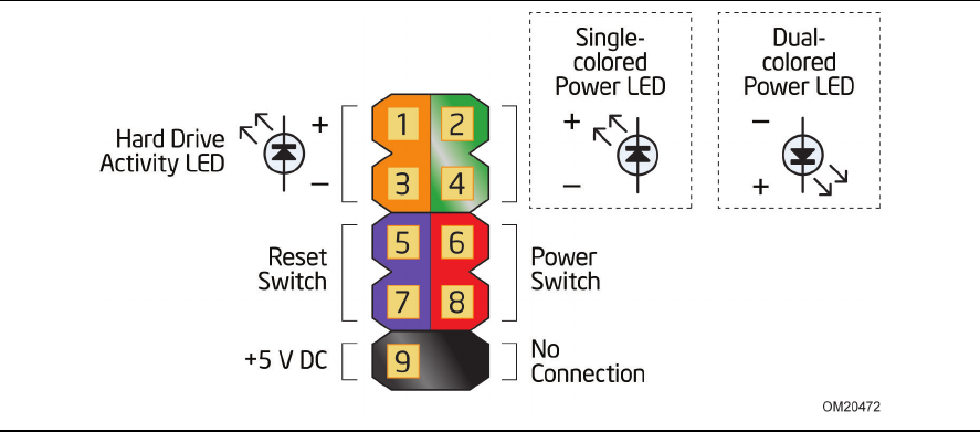
Figure 12. Connection Diagram for Front Panel Header (2.0 mm Pitch)
2.2.3.4.1 Hard Drive Activity LED Header
Pins 1 and 3 can be connected to an LED to provide a visual indicator that data is being read from
or written to a hard drive. Proper LED function requires a SATA hard drive connected to an
onboard SATA connector.
Note: When using the new M.2 SSD with PCIe there might not be any HDD activity if the storage
vendor has not implemented that function.
2.2.3.4.2 Reset Switch Header
Pins 5 and 7 can be connected to a momentary single pole, single throw (SPST) type switch that is
normally open. When the switch is closed, the board resets and runs the POST.