
Technical product specification


Technical Reference
57
Figure 15. Connection Diagram for the Internal Power Supply Connector
2.2.4.3.1 Power Sensing Circuit
The board has a power sensing circuit that:
• manages CPU power usage to maintain system power consumption below 65 W
• is designed for use with 65 W AC-DC adapters
NOTE
It is recommended that you disable this feature (via BIOS option) when using an AC-DC
adapter greater than 65 W.
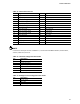
For information about
Refer to
Power supply considerations Section 2.5.1, page 66
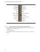
2.2.4.4 Front Panel Header (2.0 mm Pitch)
This section describes the functions of the front panel header. Table 30 lists the signal names of
the front panel header. Figure 16 is a connection diagram for the front panel header.
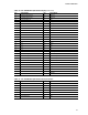
Table 30. Front Panel Header (2.0 mm Pitch)
Pin Signal Name Description Pin Signal Name Description
1 HDD_POWER_LED Pull-up resistor (750 Ω)
to +5V
2 POWER_LED_MAIN [Out] Front panel LED (main
color)
3 HDD_LED# [Out] Hard disk activity
LED
4 POWER_LED_ALT [Out] Front panel LED (alt
color)
5 GROUND Ground 6 POWER_SWITCH# [In] Power switch
7 RESET_SWITCH# [In] Reset switch 8 GROUND Ground
9 +5V_DC Power 10 Key No pin