
Technical product specification

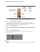
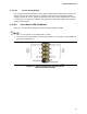


Table Of Contents
- Intel® NUC Board D33217CK Technical Product Specification
- Revision History
- Preface
- Contents
- 1 Product Description
- 2 Technical Reference
- 3 Overview of BIOS Features
- 4 Error Messages and Blink Codes
- 5 Regulatory Compliance and Battery Disposal Information
Technical Reference
41
2.2.2.3 Power Supply Connectors
The board has the following power supply connectors:
• External Power Supply – the board can be powered through a 19 V DC connector
on the back panel. The back panel DC connector is compatible with a 5.5 mm/OD
(outer diameter) and 2.5 mm/ID (inner diameter) plug, where the inner contact is
+19 (±10%) V DC and the shell is GND. The maximum current rating is 10 A.
• Internal Power Supply – the board can alternatively be powered via the internal
19 V DC 1 x 2 power connector, where pin 1 is GND and pin 2 is +19 (±10%) VDC.
Table 12. 19 V Internal Power Supply Connector
Pin Signal Name
1 Ground
2 +19 V (±10%)
For information about
Refer to
Power supply considerations Section 2.5.1, page 47
2.2.2.4 Front Panel Header
This section describes the functions of the front panel header. Table 13 lists the signal
names of the front panel header. Figure 10 is a connection diagram for the front panel
header.
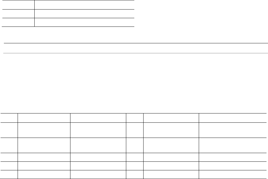
Table 13. Front Panel Header
Pin
Signal Name
Description
Pin
Signal Name
Description
1 HDD_POWER_LED Pull-up resistor
(750 Ω) to +5V
2 POWER_LED_MAIN [Out] Front panel LED
(main color)
3 HDD_LED# [Out] Hard disk
activity LED
4 POWER_LED_ALT [Out] Front panel LED
(alt color)
5 GROUND Ground 6 POWER_SWITCH# [In] Power switch
7 RESET_SWITCH# [In] Reset switch 8 GROUND Ground
9 +5V_DC Power 10 Key No pin