
Technical product specification

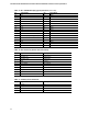
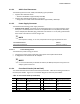
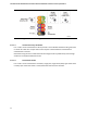


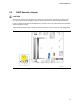

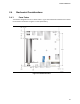
Table Of Contents
- Intel® NUC Board NUC5i5RYB and Intel® NUC Board NUC5i3RYB Technical Product Specification
- Revision History
- Contents
- 1 Product Description
- 1.1 Overview
- 1.2 Online Support
- 1.3 Processor
- 1.4 System Memory
- 1.5 Processor Graphics Subsystem
- 1.5.1 Integrated Graphics
- 1.5.1.1 Intel® High Definition (Intel® HD) Graphics
- 1.5.1.2 Video Memory Allocation
- 1.5.1.3 Mini High Definition Multimedia Interface* (Mini HDMI*)
- 1.5.1.4 Mini DisplayPort*
- 1.5.1.5 Multiple DisplayPort and HDMI Configurations
- 1.5.1.6 High-bandwidth Digital Content Protection (HDCP)
- 1.5.1.7 Integrated Audio Provided by the Mini HDMI and Mini DisplayPort Interfaces
- 1.5.1 Integrated Graphics
- 1.6 USB
- 1.7 SATA Interface
- 1.8 Real-Time Clock Subsystem
- 1.9 Audio Subsystem
- 1.10 LAN Subsystem
- 1.11 Hardware Management Subsystem
- 1.12 Power Management
- 2 Technical Reference
- 2.1 Memory Resources
- 2.2 Connectors and Headers
- 2.2.1 Front Panel Connectors
- 2.2.2 Back Panel Connectors
- 2.2.3 Connectors and Headers (Bottom)
- 2.3 BIOS Security Jumper
- 2.4 Mechanical Considerations
- 2.5 Electrical Considerations
- 2.6 Thermal Considerations
- 2.7 Reliability
- 2.8 Environmental
- 3 Overview of BIOS Features
- 4 Error Messages and Blink Codes
- 5 Regulatory Compliance and Battery Disposal Information
Technical Reference
43
2.2.3.2 Add-in Card Connectors
The board supports M.2 2242, 2260, and 2280 (key type M) modules.
• Supports M.2 SSD SATA drives
― Maximum bandwidth is approximately 540 MB/s
• Supports M.2 SSD PCIe drives (PCIe x1, x2, and x4)
― Using PCIe x4 M.2 SSD maximum bandwidth is approximately 1600 MB/s
2.2.3.3 Power Supply Connector
The board has the following power supply connector:
• External Power Supply – the board can be powered through a 12-19 V DC connector on the
back panel. The back panel DC connector is compatible with a 5.5 mm/OD (outer diameter)
and 2.5 mm/ID (inner diameter) plug, where the inner contact is +12-19 (±10%) V DC and the
shell is GND. The maximum current rating is 10 A.
NOTE
External power voltage, 12-19 V DC, is dependent on the type of power brick used.
For information about Refer to
Power supply considerations Section 2.5.1, page 50
2.2.3.3.1 Power Sensing Circuit
The board has a power sensing circuit that:
• manages CPU power usage to maintain system power consumption below 65 W.
• is designed for use with 65 W AC-DC adapters.
NOTE
It is recommended that you disable this feature (via BIOS option) when using an AC-DC
adapter greater than 65 W.
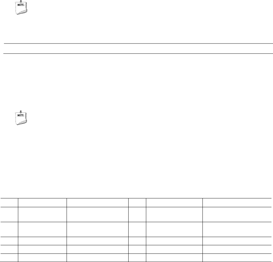
2.2.3.4 Front Panel Header (2.0 mm Pitch)
This section describes the functions of the front panel header. Table 18 lists the signal names of
the front panel header. Figure 12 is a connection diagram for the front panel header.
Table 18. Front Panel Header (2.0 mm Pitch)
Pin Signal Name Description Pin Signal Name Description
1 HDD_POWER_LED Pull-up resistor (750 Ω)
to +5V
2 POWER_LED_MAIN [Out] Front panel LED (main
color)
3 HDD_LED# [Out] Hard disk activity
LED
4 POWER_LED_ALT [Out] Front panel LED (alt
color)
5 GROUND Ground 6 POWER_SWITCH# [In] Power switch
7 RESET_SWITCH# [In] Reset switch 8 GROUND Ground
9 +5V_DC Power 10 Key No pin