
Technical product specification


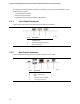

Table Of Contents
- Intel® NUC Board NUC5i5RYB and Intel® NUC Board NUC5i3RYB Technical Product Specification
- Revision History
- Contents
- 1 Product Description
- 1.1 Overview
- 1.2 Online Support
- 1.3 Processor
- 1.4 System Memory
- 1.5 Processor Graphics Subsystem
- 1.5.1 Integrated Graphics
- 1.5.1.1 Intel® High Definition (Intel® HD) Graphics
- 1.5.1.2 Video Memory Allocation
- 1.5.1.3 Mini High Definition Multimedia Interface* (Mini HDMI*)
- 1.5.1.4 Mini DisplayPort*
- 1.5.1.5 Multiple DisplayPort and HDMI Configurations
- 1.5.1.6 High-bandwidth Digital Content Protection (HDCP)
- 1.5.1.7 Integrated Audio Provided by the Mini HDMI and Mini DisplayPort Interfaces
- 1.5.1 Integrated Graphics
- 1.6 USB
- 1.7 SATA Interface
- 1.8 Real-Time Clock Subsystem
- 1.9 Audio Subsystem
- 1.10 LAN Subsystem
- 1.11 Hardware Management Subsystem
- 1.12 Power Management
- 2 Technical Reference
- 2.1 Memory Resources
- 2.2 Connectors and Headers
- 2.2.1 Front Panel Connectors
- 2.2.2 Back Panel Connectors
- 2.2.3 Connectors and Headers (Bottom)
- 2.3 BIOS Security Jumper
- 2.4 Mechanical Considerations
- 2.5 Electrical Considerations
- 2.6 Thermal Considerations
- 2.7 Reliability
- 2.8 Environmental
- 3 Overview of BIOS Features
- 4 Error Messages and Blink Codes
- 5 Regulatory Compliance and Battery Disposal Information

37
2 Technical Reference
2.1 Memory Resources
2.1.1 Addressable Memory
The board utilizes 16 GB of addressable system memory. Typically the address space that is
allocated for PCI Conventional bus add-in cards, PCI Express configuration space, BIOS (SPI Flash
device), and chipset overhead resides above the top of DRAM (total system memory). On a system
that has 32 GB of system memory installed, it is not possible to use all of the installed memory
due to system address space being allocated for other system critical functions. These functions
include the following:
• BIOS/SPI Flash device (64 Mb)
• Local APIC (19 MB)
• Direct Media Interface (40 MB)
• PCI Express configuration space (256 MB)
• PCH base address registers PCI Express ports (up to 256 MB)
• Memory-mapped I/O that is dynamically allocated for M.2 add-in cards (256 MB)
• Integrated graphics shared memory (up to 512 MB; 64 MB by default)
The board provides the capability to reclaim the physical memory overlapped by the memory
mapped I/O logical address space. The board remaps physical memory from the top of usable
DRAM boundary to the 4 GB boundary to an equivalent sized logical address range located just
above the 4 GB boundary. All installed system memory can be used when there is no overlap of
system addresses.
2.2 Connectors and Headers
CAUTION
Only the following connectors and headers have overcurrent protection: back panel and front
panel USB.
The other internal connectors and headers are not overcurrent protected and should connect only
to devices inside the computer’s chassis, such as fans and internal peripherals. Do not use these
connectors or headers to power devices external to the computer’s chassis. A fault in the load
presented by the external devices could cause damage to the computer, the power cable, and the
external devices themselves.
Furthermore, improper connection of USB header single wire connectors may eventually overload
the overcurrent protection and cause damage to the board.