
Technical product specification


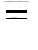
Table Of Contents
- Intel® NUC Board NUC5i5RYB and Intel® NUC Board NUC5i3RYB Technical Product Specification
- Revision History
- Contents
- 1 Product Description
- 1.1 Overview
- 1.2 Online Support
- 1.3 Processor
- 1.4 System Memory
- 1.5 Processor Graphics Subsystem
- 1.5.1 Integrated Graphics
- 1.5.1.1 Intel® High Definition (Intel® HD) Graphics
- 1.5.1.2 Video Memory Allocation
- 1.5.1.3 Mini High Definition Multimedia Interface* (Mini HDMI*)
- 1.5.1.4 Mini DisplayPort*
- 1.5.1.5 Multiple DisplayPort and HDMI Configurations
- 1.5.1.6 High-bandwidth Digital Content Protection (HDCP)
- 1.5.1.7 Integrated Audio Provided by the Mini HDMI and Mini DisplayPort Interfaces
- 1.5.1 Integrated Graphics
- 1.6 USB
- 1.7 SATA Interface
- 1.8 Real-Time Clock Subsystem
- 1.9 Audio Subsystem
- 1.10 LAN Subsystem
- 1.11 Hardware Management Subsystem
- 1.12 Power Management
- 2 Technical Reference
- 2.1 Memory Resources
- 2.2 Connectors and Headers
- 2.2.1 Front Panel Connectors
- 2.2.2 Back Panel Connectors
- 2.2.3 Connectors and Headers (Bottom)
- 2.3 BIOS Security Jumper
- 2.4 Mechanical Considerations
- 2.5 Electrical Considerations
- 2.6 Thermal Considerations
- 2.7 Reliability
- 2.8 Environmental
- 3 Overview of BIOS Features
- 4 Error Messages and Blink Codes
- 5 Regulatory Compliance and Battery Disposal Information

Product Description
33
1.12.1.1 System States and Power States
Under ACPI, the operating system directs all system and device power state transitions. The
operating system puts devices in and out of low-power states based on user preferences and
knowledge of how devices are being used by applications. Devices that are not being used can be
turned off. The operating system uses information from applications and user settings to put the
system as a whole into a low-power state.
Table 10 lists the power states supported by the board along with the associated system power
targets. See the ACPI specification for a complete description of the various system and power
states.
Table 10. Power States and Targeted System Power
Global States
Sleeping States
Processor
States
Device States
Targeted System
Power
(Note 1)
G0 – working
state
S0 – working C0 – working D0 – working state. Full power > 30 W
G1 – sleeping
state
S3 – Suspend to RAM.
Context saved to
RAM.
No power D3 – no power
except for wake-up
logic.
Power < 5 W
(Note 2)
G1 – sleeping
state
S4 – Suspend to disk.
Context saved to disk.
No power D3 – no power
except for wake-up
logic.
Power < 5 W
(Note 2)
G2/S5 S5 – Soft off. Context
not saved. Cold boot
is required.
No power D3 – no power
except for wake-up
logic.
Power < 5 W
(Note 2)
G3 – mechanical
off
AC power is
disconnected
from the
computer.
No power to the
system.
No power D3 – no power for
wake-up logic,
except when
provided by battery
or external source.
No power to the system.
Service can be performed
safely.
Notes:
1. Total system power is dependent on the system configuration, including add-in boards and peripherals powered by
the system chassis’ power supply.
2. Dependent on the standby power consumption of wake-up devices used in the system.