
Technical product specification


Product Description
25
1.6 USB
The USB port arrangement is as follows:
• One USB 3.0 front panel connector
• Two USB 2.0 back panel connectors
• Two front panel USB 2.0 ports are implemented through a dual-port internal header
• One front panel USB 2.0 port is implemented through a single-port internal header
• One port is reserved for the PCI Express* Half-Mini Card
All the USB ports are high-speed, full-speed, and low-speed capable.
NOTE
Computer systems that have an unshielded cable attached to a USB port may not meet FCC
Class B requirements, even if no device is attached to the cable. Use a shielded cable that meets
the requirements for full-speed devices.
For information about
Refer to
The location of the USB connectors on the back panel Figure 11, page 38
The location of the USB connector on the front panel Figure 2, page 15
1.7 SATA Interface
The SoC provides one SATA port with a theoretical maximum transfer rate of 3 Gb/s. A point-to-
point interface is used for host to device connections.
The underlying SATA functionality is transparent to the operating system. The SATA controller
can operate in both legacy and native modes. In legacy mode, standard IDE I/O and IRQ resources
are assigned (IRQ 14 and 15). In Native mode, standard PCI Conventional bus resource steering is
used. Native mode is the preferred mode for configurations using Windows operating systems.
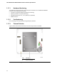
1.7.1 SATA Disk-on-Module (DOM) Voltage Selection Header
The board provides support for SATA Disk-on-Module (DOM) via a user-selectable voltage level
on SATA data pin 7. See Table 5 for more details.
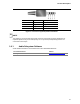
Table 5. SATA DOM Voltage Selection Header
Pins 1 and 2 jumper position for 5 V
Pins 3 and 2 jumper position for GND
(default)