
Product Guide for Intel Desktop Board D2700DC


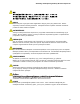


Table Of Contents
- Intel® Desktop Board D2700DC Product Guide
- Revision History
- Preface
- 1 Desktop Board Features
- Operating System Support
- Desktop Board Components
- Processor
- System Memory
- Graphics Support
- Intel® NM10 Express Chipset
- Onboard Audio Subsystem
- Legacy Input/Output (I/O) Controller
- LAN Subsystem
- USB 2.0 Support
- SATA Interface
- Expandability
- BIOS
- Hardware Management Features
- Power Management Features
- Battery
- Real-Time Clock
- 2 Installing and Replacing Desktop Board Components
- Before You Begin
- Installation Precautions
- Installing the I/O Shield
- Installing and Removing the Desktop Board
- Installing and Removing Memory
- Connecting SATA Drives
- Installing a PCI Express Mini Card
- Installing an Intel® Z-U130 USB Solid-State Drive or Compatible Device
- Connecting to the Internal Headers
- Connecting a System Fan
- Connecting a Power Supply
- Setting the BIOS Configuration Jumper
- Replacing the Battery
- 3 Updating the BIOS
- A Board Status and Error Messages
- B Regulatory Compliance
Installing and Replacing Desktop Board Components
45
1. Observe the precautions in "Before You Begin" (see page 23).
2. Turn off all peripheral devices connected to the computer. Disconnect the
computer’s power cord from the AC power source (wall outlet or power adapter).
3. Remove the computer cover.
4. Locate the battery on the board (see Figure 15).
5. P
ush the battery retention clip aside and remove the battery from the connector as
shown in Figure 15. Note the orientation of the “+” and “-” on the battery.
6. Instal
l the new battery in the connector, making sure to orient the “+” and “-”
correctly.
7. Replace the computer cover.
Figure 15. Removing the Battery