
Product Guide for Intel Desktop Board D2700DC


Table Of Contents
- Intel® Desktop Board D2700DC Product Guide
- Revision History
- Preface
- 1 Desktop Board Features
- Operating System Support
- Desktop Board Components
- Processor
- System Memory
- Graphics Support
- Intel® NM10 Express Chipset
- Onboard Audio Subsystem
- Legacy Input/Output (I/O) Controller
- LAN Subsystem
- USB 2.0 Support
- SATA Interface
- Expandability
- BIOS
- Hardware Management Features
- Power Management Features
- Battery
- Real-Time Clock
- 2 Installing and Replacing Desktop Board Components
- Before You Begin
- Installation Precautions
- Installing the I/O Shield
- Installing and Removing the Desktop Board
- Installing and Removing Memory
- Connecting SATA Drives
- Installing a PCI Express Mini Card
- Installing an Intel® Z-U130 USB Solid-State Drive or Compatible Device
- Connecting to the Internal Headers
- Connecting a System Fan
- Connecting a Power Supply
- Setting the BIOS Configuration Jumper
- Replacing the Battery
- 3 Updating the BIOS
- A Board Status and Error Messages
- B Regulatory Compliance
Installing and Replacing Desktop Board Components
39
Setting the BIOS Configuration Jumper
NOTE
Always turn off the power and unplug the power cord from the computer before
changing the jumper. Moving the jumper with the power on may result in unreliable
computer operation.
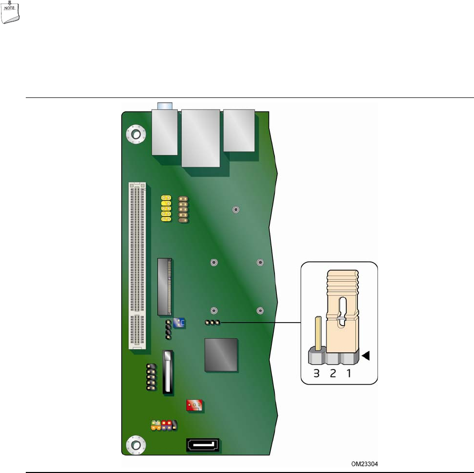
Figure 14 shows the location of the Desktop Board’s BIOS confi
guration jumper block.
Figure 14. BIOS Configuration Jumper Block
The three-pin BIOS configuration jumper block enables board operating modes.
Table 12 shows the jumper settings for each
of the available modes.