
Product Guide for Intel Desktop Board D2700DC


Table Of Contents
- Intel® Desktop Board D2700DC Product Guide
- Revision History
- Preface
- 1 Desktop Board Features
- Operating System Support
- Desktop Board Components
- Processor
- System Memory
- Graphics Support
- Intel® NM10 Express Chipset
- Onboard Audio Subsystem
- Legacy Input/Output (I/O) Controller
- LAN Subsystem
- USB 2.0 Support
- SATA Interface
- Expandability
- BIOS
- Hardware Management Features
- Power Management Features
- Battery
- Real-Time Clock
- 2 Installing and Replacing Desktop Board Components
- Before You Begin
- Installation Precautions
- Installing the I/O Shield
- Installing and Removing the Desktop Board
- Installing and Removing Memory
- Connecting SATA Drives
- Installing a PCI Express Mini Card
- Installing an Intel® Z-U130 USB Solid-State Drive or Compatible Device
- Connecting to the Internal Headers
- Connecting a System Fan
- Connecting a Power Supply
- Setting the BIOS Configuration Jumper
- Replacing the Battery
- 3 Updating the BIOS
- A Board Status and Error Messages
- B Regulatory Compliance
Intel Desktop Board D2700DC Product Guide
38
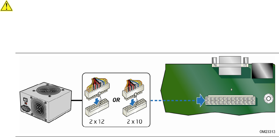
Connecting a Power Supply
CAUTION
Failure to connect an appropriate power supply to the Desktop Board may result in
damage to the board or the system may not function properly.
Figure 13 shows the location of the power connector.
Figure 13. Connecting Power Supply Cables
1. Observe the precautions in "Before You Begin" on page 23.
2. Connect the main power supply cable to the 2 x 12 pin connector.