
Product Guide for Intel Desktop Board D2700DC


Table Of Contents
- Intel® Desktop Board D2700DC Product Guide
- Revision History
- Preface
- 1 Desktop Board Features
- Operating System Support
- Desktop Board Components
- Processor
- System Memory
- Graphics Support
- Intel® NM10 Express Chipset
- Onboard Audio Subsystem
- Legacy Input/Output (I/O) Controller
- LAN Subsystem
- USB 2.0 Support
- SATA Interface
- Expandability
- BIOS
- Hardware Management Features
- Power Management Features
- Battery
- Real-Time Clock
- 2 Installing and Replacing Desktop Board Components
- Before You Begin
- Installation Precautions
- Installing the I/O Shield
- Installing and Removing the Desktop Board
- Installing and Removing Memory
- Connecting SATA Drives
- Installing a PCI Express Mini Card
- Installing an Intel® Z-U130 USB Solid-State Drive or Compatible Device
- Connecting to the Internal Headers
- Connecting a System Fan
- Connecting a Power Supply
- Setting the BIOS Configuration Jumper
- Replacing the Battery
- 3 Updating the BIOS
- A Board Status and Error Messages
- B Regulatory Compliance
Intel Desktop Board D2700DC Product Guide
36
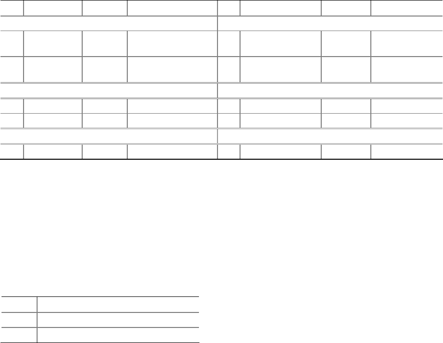
Connecting to the Front Panel Header
Before connecting to the front panel header, observe the precautions in "Before You
Begin" on page 23. See Figure 11, D for the location of the front panel header.
Table 10 shows the pin assignments for t
he front panel header.
Table 10. Front Panel Header
Pin Signal In/Out Description Pin
Signal In/Out Description
Hard Drive Activity LED Power LED
1 HD_PWR Out
Hard disk LED pull-
up (330 Ω) to +5 V
2 HDR_BLNK_GRN Out
Front panel
green LED
3 HDA# Out
Hard disk active
LED
4 HDR_BLNK_YEL Out
Front panel
yellow LED
Reset Switch On/Off Switch
5 Ground Ground 6 SWITCH_ON# In Power switch
7 FP_RESET# In Reset switch 8 Ground Ground
Power Not Connected
9 +5 V Power 10 N/C No pin
Connecting to the Front Panel Wireless Activity LED
Header
Before connecting to the front panel wireless activity LED header, observe the
precautions in "Before You Begin" on page 23. See Figure 11, F for the location of the
front
panel wireless activity LED header.
Table 11 shows the pin assignments for the f
ront panel wireless activity LED header.
Table 11. Front Panel Wireless Activity LED Header
Pin Signal Name
1 Ground
2 MINICARD_WLAN#