
Product Guide for Intel Desktop Board D2700DC


Table Of Contents
- Intel® Desktop Board D2700DC Product Guide
- Revision History
- Preface
- 1 Desktop Board Features
- Operating System Support
- Desktop Board Components
- Processor
- System Memory
- Graphics Support
- Intel® NM10 Express Chipset
- Onboard Audio Subsystem
- Legacy Input/Output (I/O) Controller
- LAN Subsystem
- USB 2.0 Support
- SATA Interface
- Expandability
- BIOS
- Hardware Management Features
- Power Management Features
- Battery
- Real-Time Clock
- 2 Installing and Replacing Desktop Board Components
- Before You Begin
- Installation Precautions
- Installing the I/O Shield
- Installing and Removing the Desktop Board
- Installing and Removing Memory
- Connecting SATA Drives
- Installing a PCI Express Mini Card
- Installing an Intel® Z-U130 USB Solid-State Drive or Compatible Device
- Connecting to the Internal Headers
- Connecting a System Fan
- Connecting a Power Supply
- Setting the BIOS Configuration Jumper
- Replacing the Battery
- 3 Updating the BIOS
- A Board Status and Error Messages
- B Regulatory Compliance
Installing and Replacing Desktop Board Components
35
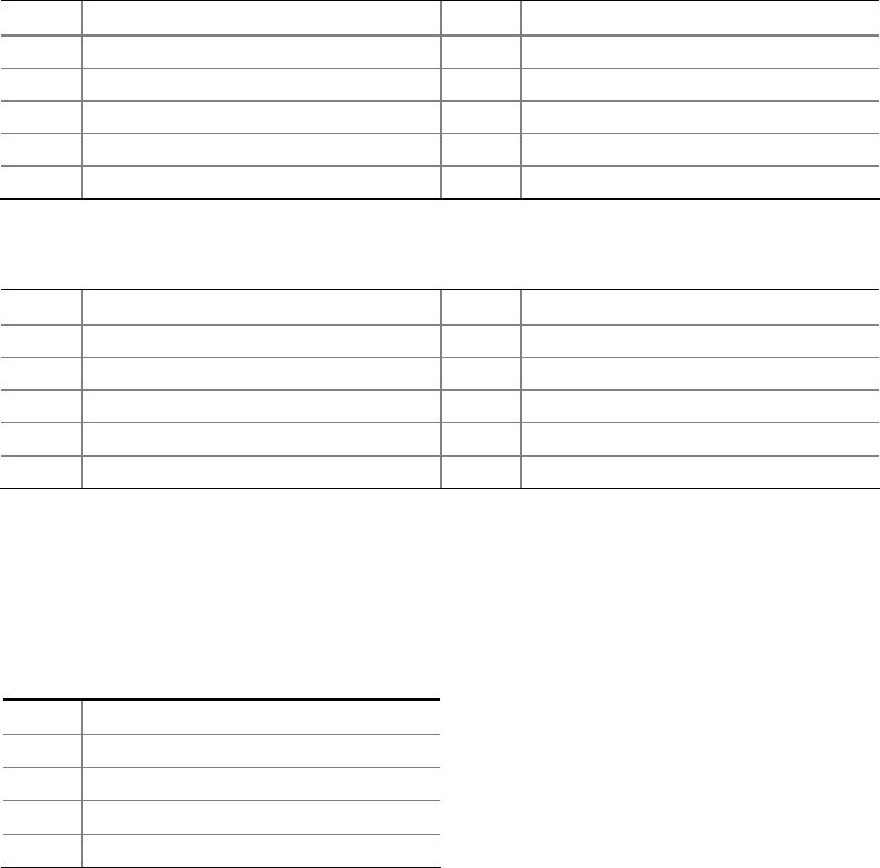
Connecting to the Front Panel USB 2.0 Headers
Before connecting to the USB 2.0 headers, observe the precautions in "Before You
Begin" on page 23. See Figure 11, B and E for the location of the
USB 2.0 headers.
Table 7 and Table 8 show the pin assignments for the
headers.
The brown USB header (Figure 11, B) supports a single USB port while the black
USB
header (Figure 11, E) supports two USB ports. The
single USB port header is designed
to support a Flash Memory Drive such as the Intel Z-U130 USB Solid-State Drive (or
compatible device). Refer to “Installing an Intel
®
Z-U130 USB Solid-State Drive or
Compatible Device” on page 32 for more information.
Table 7.
Front Panel USB Header
Pin Signal Name Pin Signal Name
1
+5 VDC
2
+5 VDC
3
D-
4
D-
5
D+
6
D+
7
Ground
8
Ground
9
KEY (no pin)
10
No Connect
Table 8. Front Panel USB Header with Intel Z-U130 USB Solid-State Drive or
Compatible Device Support
Pin Signal Name Pin Signal Name
1
+5 VDC
2
No Connect
3
D-
4
No Connect
5
D+
6
No Connect
7
Ground
8
No Connect
9
KEY (no pin)
10
LED#
Connecting to the Piezoelectric Speaker Header
Figure 11, C shows the location of the piezoelectric speaker header. Table 9 shows the
pin assignments for the piezoelectric speaker header.
Table 9. Piezoelectric Speaker Header
Pin Signal Name
1 + 5 VDC
2 Key (no pin)
3 Key (no pin)
4 SPKR