
Product Guide for Intel Desktop Board D2700DC


Table Of Contents
- Intel® Desktop Board D2700DC Product Guide
- Revision History
- Preface
- 1 Desktop Board Features
- Operating System Support
- Desktop Board Components
- Processor
- System Memory
- Graphics Support
- Intel® NM10 Express Chipset
- Onboard Audio Subsystem
- Legacy Input/Output (I/O) Controller
- LAN Subsystem
- USB 2.0 Support
- SATA Interface
- Expandability
- BIOS
- Hardware Management Features
- Power Management Features
- Battery
- Real-Time Clock
- 2 Installing and Replacing Desktop Board Components
- Before You Begin
- Installation Precautions
- Installing the I/O Shield
- Installing and Removing the Desktop Board
- Installing and Removing Memory
- Connecting SATA Drives
- Installing a PCI Express Mini Card
- Installing an Intel® Z-U130 USB Solid-State Drive or Compatible Device
- Connecting to the Internal Headers
- Connecting a System Fan
- Connecting a Power Supply
- Setting the BIOS Configuration Jumper
- Replacing the Battery
- 3 Updating the BIOS
- A Board Status and Error Messages
- B Regulatory Compliance
Intel Desktop Board D2700DC Product Guide
32
Installing an Intel
®
Z-U130 USB Solid-State
Drive or Compatible Device
An Intel Z-U130 USB Solid-State Drive or compatible device can be installed on the
Desktop Board by using the onboard USB 2.0 header shown in Figure 1, S. This
h
eader provides support for the solid-state drive.
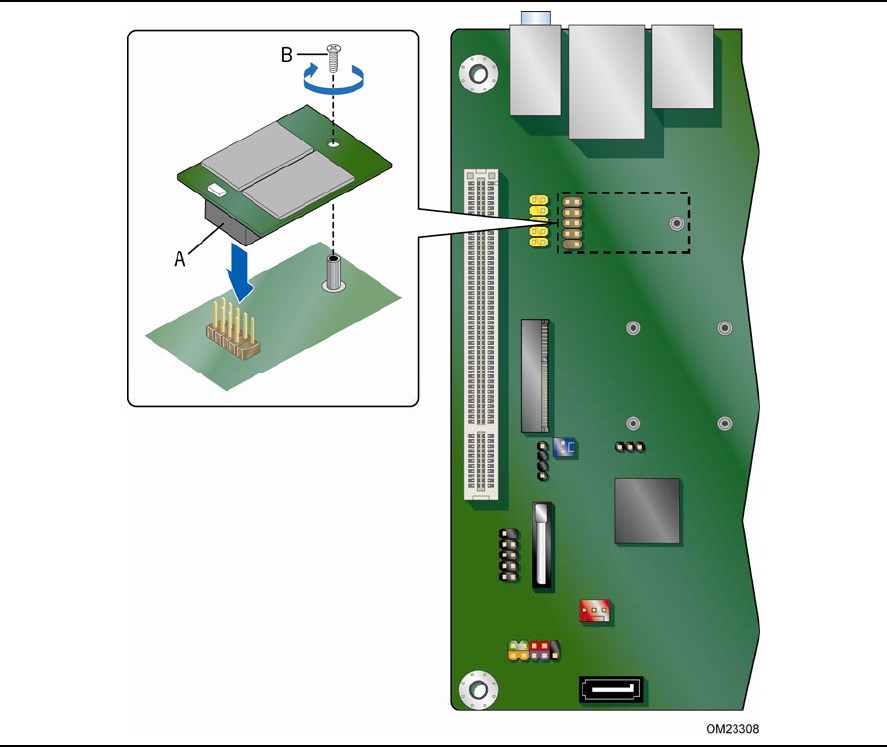
To install an Intel Z-U130 USB Solid-State Drive or compatible device on the Desktop
Board, follow these steps:
1. Observe the precautions in "Before You Begin" on page 23.
2. Al
ign the connector (Figure 10, A) on the bottom of the solid state drive with
the
USB 2.0 header on the Desktop Board. The connectors are keyed and will mate
correctly when the solid state drive is oriented as shown in Figure 10.
3. Secure the
solid state drive to the Desktop Board with the provided screw
(Figure 10, B).
Figure 10. Installing an Intel Z-U130 USB Solid-State Drive
(or Compatible Device)