
Product Guide for Intel Desktop Board D2700DC


Table Of Contents
- Intel® Desktop Board D2700DC Product Guide
- Revision History
- Preface
- 1 Desktop Board Features
- Operating System Support
- Desktop Board Components
- Processor
- System Memory
- Graphics Support
- Intel® NM10 Express Chipset
- Onboard Audio Subsystem
- Legacy Input/Output (I/O) Controller
- LAN Subsystem
- USB 2.0 Support
- SATA Interface
- Expandability
- BIOS
- Hardware Management Features
- Power Management Features
- Battery
- Real-Time Clock
- 2 Installing and Replacing Desktop Board Components
- Before You Begin
- Installation Precautions
- Installing the I/O Shield
- Installing and Removing the Desktop Board
- Installing and Removing Memory
- Connecting SATA Drives
- Installing a PCI Express Mini Card
- Installing an Intel® Z-U130 USB Solid-State Drive or Compatible Device
- Connecting to the Internal Headers
- Connecting a System Fan
- Connecting a Power Supply
- Setting the BIOS Configuration Jumper
- Replacing the Battery
- 3 Updating the BIOS
- A Board Status and Error Messages
- B Regulatory Compliance
Installing and Replacing Desktop Board Components
27
Installing and Removing the Desktop Board
CAUTION
Only qualified technical personnel should do this procedure. Disconnect the computer
from its power source before performing the procedures described here. Failure to
disconnect the power before you open the computer can result in personal injury or
equipment damage.
Refer to your chassis manual for instructions on installing and removing the Desktop
Board.
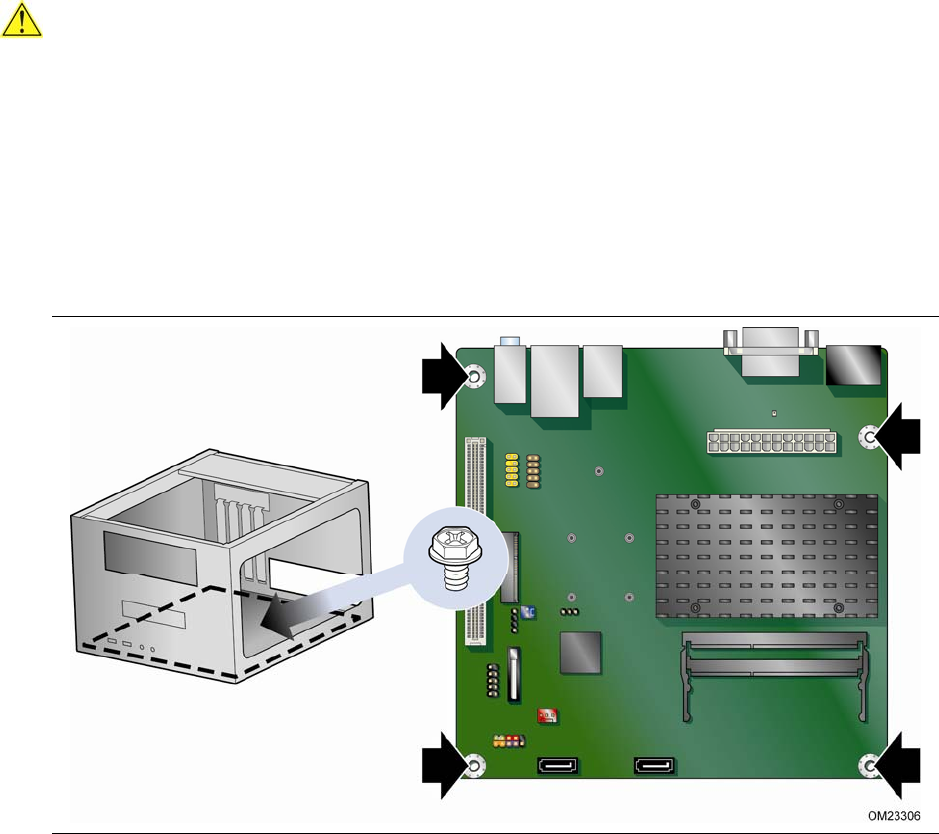
Figure 6 shows the location of the mounti
ng screw holes for Intel Desktop Board
D2700DC.
Figure 6. Intel Desktop Board D2700DC Mounting Screw Holes