
Product Guide for Intel Desktop Board D2700DC


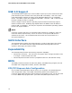


Table Of Contents
- Intel® Desktop Board D2700DC Product Guide
- Revision History
- Preface
- 1 Desktop Board Features
- Operating System Support
- Desktop Board Components
- Processor
- System Memory
- Graphics Support
- Intel® NM10 Express Chipset
- Onboard Audio Subsystem
- Legacy Input/Output (I/O) Controller
- LAN Subsystem
- USB 2.0 Support
- SATA Interface
- Expandability
- BIOS
- Hardware Management Features
- Power Management Features
- Battery
- Real-Time Clock
- 2 Installing and Replacing Desktop Board Components
- Before You Begin
- Installation Precautions
- Installing the I/O Shield
- Installing and Removing the Desktop Board
- Installing and Removing Memory
- Connecting SATA Drives
- Installing a PCI Express Mini Card
- Installing an Intel® Z-U130 USB Solid-State Drive or Compatible Device
- Connecting to the Internal Headers
- Connecting a System Fan
- Connecting a Power Supply
- Setting the BIOS Configuration Jumper
- Replacing the Battery
- 3 Updating the BIOS
- A Board Status and Error Messages
- B Regulatory Compliance

Intel Desktop Board D2700DC Product Guide
20
ACPI
ACPI gives the operating system direct control over the power management and Plug
and Play functions of a computer. The use of ACPI with the Desktop Board requires an
operating system that provides full ACPI support.
Hardware Support
Fan Header
The Desktop Board has a 3-pin system fan header. See Figure 12 on page 37 for the
location of the system fan header.
+5 V Standby Power Indicator
CAUTION
If the AC power has been switched off and the standby power indicator is still lit,
disconnect the power cord before installing or removing any devices connected to the
board. Failure to do so could damage the board and any attached devices.
The Desktop Board’s standby power indicator, shown in Figure 4, is lit when there is
standby power to the system. This includes the SO-DIMM sockets and the PCI bus
connector, even though the computer appears to be off.