Intel® Desktop Board D2550DC2 Product Guide Order Number: G74459-001
Revision History Revision -001 Revision History First release of the Intel® Desktop Board D2550DC2 Product Guide Date August 2012 Disclaimer Information in this document is provided in connection with Intel® products. No license, express or implied, by estoppel or otherwise, to any intellectual property rights is granted by this document.
Preface This Product Guide gives information about board layout, component installation, and regulatory requirements for Intel® Desktop Board D2550DC2. Intended Audience The Product Guide is intended for technically qualified personnel. It is not intended for general audiences. Intended Uses All Intel® Desktop Boards are evaluated as Information Technology Equipment (I.T.E.) for use in personal computers (PC) for installation in homes, offices, schools, computer rooms, and similar locations.
Intel Desktop Board D2550DC2 Product Guide Terminology The table below gives descriptions to some common terms used in the product guide.
Contents 1 Desktop Board Features Operating System Support ................................................................................... 10 Desktop Board Components.................................................................................. 11 Processor ........................................................................................................... 13 System Memory .................................................................................................. 13 Graphics Support ..
Intel Desktop Board D2550DC2 Product Guide 3 Updating the BIOS Updating the BIOS with the Intel® Express BIOS Update Utility ................................. 47 Updating the BIOS Using the F7 Function Key ......................................................... 48 Updating the BIOS with the Iflash Memory Update Utility ......................................... 48 Obtaining the BIOS Update File .....................................................................
Contents Figures 1. 2. 3. 4. 5. 6. 7. 8. 9. 10. 11. 12. 13. 14. 15. 16. Intel Desktop Board D2550DC2 Components..................................................... 11 Back Panel Audio Connectors .......................................................................... 16 LAN Status LEDs ............................................................................................ 17 Location of the Standby Power Indicator ...........................................................
Intel Desktop Board D2550DC2 Product Guide viii
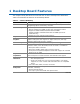
1 Desktop Board Features This chapter briefly describes the main features of Intel® Desktop Board D2550DC2. Table 1 summarizes the features of the Desktop Board. Table 1. Feature Summary Form Factor Processor Main Memory Chipset Integrated Graphics External Graphics Audio Expansion Capabilities Peripheral Interfaces Hardware Monitor Subsystem Mini-ITX (170 millimeters [6.7 inches] x 170 millimeters [6.
Intel Desktop Board D2550DC2 Product Guide Table 1.
Desktop Board Features Desktop Board Components Figure 1 shows the location of the major components on Intel Desktop Board D2550DC2. Figure 1.
Intel Desktop Board D2550DC2 Product Guide Table 2.
Desktop Board Features Processor Intel Desktop Board D2550DC2 includes a passively-cooled, dual-core Intel Atom processor with integrated graphics and memory controller. The processor is soldered to the Desktop Board and is not customer upgradeable. NOTE The board is designed to be passively cooled in a properly ventilated chassis. Chassis venting locations are recommended above the processor heatsink area for maximum heat dissipation effectiveness.
Intel Desktop Board D2550DC2 Product Guide Graphics Support Integrated Graphics Subsystem The Intel GMA 3650 integrated graphics subsystem features the following: • • • 640 MHz core frequency High quality texture engine DX10.1c* and OpenGL* 3.0 compliant Hardware Pixel Shader 4.1 Vertex Shader Model 4.1 Video Blu-ray* 2.0 J.264 and VC1 hardware decoder PAVP 1.1c • HDCP 1.
Desktop Board Features Intel® NM10 Express Chipset The Intel NM10 Express Chipset is a centralized controller for the board’s I/O paths. For more information about the Intel NM10 Express Chipset, go to http://www.intel.com/products/chipsets/index.htm?iid=prod+prod_chipset. Onboard Audio Subsystem The onboard audio subsystem supports both Intel HD Audio and AC ’97 Audio.
Intel Desktop Board D2550DC2 Product Guide Figure 2 shows the default assignment of the back panel audio connectors. Item Description A Line In B Line Out C Mic In Figure 2. Back Panel Audio Connectors NOTE The back panel audio line out connector is designed to power amplified speakers or headphones only. Poor audio quality occurs if passive (non-amplified) speakers are connected to this output.
Desktop Board Features LAN Subsystem The LAN subsystem consists of the following: • • • Intel NM10 Express Chipset Intel 82574L Gigabit Ethernet Controller for 10/100/1000 Mb/s Ethernet LAN connectivity RJ-45 LAN connector with integrated status LEDs Additional features of the LAN subsystem include: • • • CSMA/CD protocol engine LAN connect interface that supports the Ethernet controller Conventional PCI bus power management Supports ACPI technology Supports LAN wake capabilities LAN drivers are av
Intel Desktop Board D2550DC2 Product Guide USB 2.0 Support The Desktop Board supports up to seven USB 2.0 ports (four ports routed to the back panel and three ports routed to two front panel USB 2.0 headers). One of the front panel USB headers supports an Intel Z-U130 USB Solid-State Drive or compatible device. The USB 2.0 ports are compatible with USB 1.1 devices. USB 1.1 devices will function normally at USB 1.1 speeds. USB 2.
Desktop Board Features Security Passwords The BIOS includes security features that restrict whether the BIOS Setup program can be accessed and who can boot the computer. A supervisor password and a user password can be set for the BIOS Setup and for booting the computer, with the following restrictions: • • • The supervisor password gives unrestricted access to view and change all Setup options.
Intel Desktop Board D2550DC2 Product Guide ACPI ACPI gives the operating system direct control over the power management and Plug and Play functions of a computer. The use of ACPI with the Desktop Board requires an operating system that provides full ACPI support. Hardware Support Fan Header The Desktop Board has a 3-pin system fan header. See Figure 12 on page 37 for the location of the system fan header.
Desktop Board Features Figure 4. Location of the Standby Power Indicator For more information on standby current requirements for the Desktop Board, refer to the Technical Product Specification on the Intel Desktop D2550DC2 web page at http://www.intel.com/products/motherboard/index.htm. Instantly Available PC Technology Instantly Available PC technology enables the board to enter the ACPI S3 (Suspend-toRAM) sleep-state.
Intel Desktop Board D2550DC2 Product Guide LAN Wake Capabilities The board’s LAN wake capabilities enable remote wake-up of the computer through a network. The LAN subsystem network adapter monitors network traffic at the Media Independent Interface. The board supports LAN wake capabilities with ACPI in the following ways: • • By Ping By Magic Packet Upon detecting the configured wake packet type, the LAN subsystem asserts a wakeup signal that powers up the computer.
2 Installing and Replacing Desktop Board Components This chapter tells you how to: • • • • • • • • • • • Install the I/O shield Install and remove the Desktop Board Install and remove system memory Connect SATA drives Install a PCI Express Mini Card Install an Intel Z-U130 USB Solid-State Drive or compatible device Connect to internal headers Connect system fan and power supply cables Set the BIOS configuration jumper Clear passwords Replace the battery Before You Begin CAUTION The procedures in this chap
Intel Desktop Board D2550DC2 Product Guide CAUTION Failure to ensure appropriate airflow may result in reduced performance of both the processor and/or voltage regulator or, in some instances, damage to the board. All responsibility for determining the adequacy of any thermal or system design remains solely with the reader. Intel makes no warranties or representations that merely following the instructions presented in this document will result in a system with adequate thermal performance.
Installing and Replacing Desktop Board Components Installation Precautions When you install and test the Intel Desktop Board, observe all warnings and cautions in the installation instructions.
Intel Desktop Board D2550DC2 Product Guide Installing the I/O Shield The Desktop Board comes with an I/O shield. When installed in the chassis, the shield blocks radio frequency transmissions, protects internal components from dust and foreign objects, and promotes correct airflow within the chassis. Install the I/O shield before installing the Desktop Board in the chassis. Place the shield inside the chassis as shown in Figure 5. Press the shield into place so that it fits tightly and securely.
Installing and Replacing Desktop Board Components Installing and Removing the Desktop Board CAUTION Only qualified technical personnel should do this procedure. Disconnect the computer from its power source before performing the procedures described here. Failure to disconnect the power before you open the computer can result in personal injury or equipment damage. Refer to your chassis manual for instructions on installing and removing the Desktop Board.
Intel Desktop Board D2550DC2 Product Guide Installing and Removing Memory NOTE To be fully compliant with all applicable Intel SDRAM memory specifications, the boards require SO-DIMMs that support the Serial Presence Detect (SPD) data structure. The Desktop Board has two 204-pin DDR3 SO-DIMM sockets that support up to 4 GB of system memory. To install system memory on the Desktop Board, see Figure 7 and follow these steps: 1. Observe the precautions in "Before You Begin" on page 23. 2.
Installing and Replacing Desktop Board Components Connecting SATA Drives The board has two SATA connectors each supporting one SATA drive. The included SATA cables support the Serial ATA protocol. For correct cable and drive function: 1. Observe the precautions in "Before You Begin" on page 23. 2. Attach one end of the cable to the connector on the board (Figure 8, A) and connect the other end to the drive (Figure 8, B). Figure 8.
Intel Desktop Board D2550DC2 Product Guide Installing a PCI Express Mini Card You can install a PCI Express Full-Mini Card or a PCI Express Half-Mini Card in the Desktop Board’s PCI Express Mini Card slot. To install a Full-Mini Card, see Figure 9 and follow these steps: 1. Observe the precautions in "Before You Begin" on page 23. 2. Insert the card into the PCI Express Mini Card connector (Figure 9, A) at a slightly upward angle. 3.
Installing and Replacing Desktop Board Components Figure 9.
Intel Desktop Board D2550DC2 Product Guide Installing an Intel® Z-U130 USB Solid-State Drive or Compatible Device An Intel Z-U130 USB Solid-State Drive or compatible device can be installed on the Desktop Board by using the onboard USB 2.0 header shown in Figure 1, S. This header provides support for the solid-state drive. To install an Intel Z-U130 USB Solid-State Drive or compatible device on the Desktop Board, follow these steps: 1. Observe the precautions in "Before You Begin" on page 23. 2.
Installing and Replacing Desktop Board Components Connecting to the Internal Headers Before connecting cables to the internal headers, observe the precautions in "Before You Begin" on page 23. Figure 11 shows the location of the board’s internal headers. Figure 11.
Intel Desktop Board D2550DC2 Product Guide Connecting to the Front Panel Audio Header Figure 11, A shows the location of the front panel audio header. The front panel audio header can be used for both Intel HD Audio and AC ‘97 Audio. Table 5 shows the pin assignments for the Intel HD Audio and Table 6 shows the pin assignments for AC ‘97 Audio. Table 5.
Installing and Replacing Desktop Board Components Connecting to the Front Panel USB 2.0 Headers Before connecting to the USB 2.0 headers, observe the precautions in "Before You Begin" on page 23. See Figure 11, B and E for the location of the USB 2.0 headers. Table 7 and Table 8 show the pin assignments for the headers. The brown USB header (Figure 11, B) supports a single USB port while the black USB header (Figure 11, E) supports two USB ports.
Intel Desktop Board D2550DC2 Product Guide Connecting to the Front Panel Header Before connecting to the front panel header, observe the precautions in "Before You Begin" on page 23. See Figure 11, D for the location of the front panel header. Table 10 shows the pin assignments for the front panel header. Table 10.
Installing and Replacing Desktop Board Components Connecting a System Fan Figure 12 shows the location of the system fan header. Connect the system fan cable to this header. Figure 12.
Intel Desktop Board D2550DC2 Product Guide Connecting a Power Supply CAUTION Failure to connect an appropriate power supply to the Desktop Board may result in damage to the board or the system may not function properly. Figure 13 shows the location of the power connector. Figure 13. Connecting Power Supply Cables 1. Observe the precautions in "Before You Begin" on page 23. 2. Connect the main power supply cable to the 2 x 12 pin connector.
Installing and Replacing Desktop Board Components Setting the BIOS Configuration Jumper NOTE Always turn off the power and unplug the power cord from the computer before changing the jumper. Moving the jumper with the power on may result in unreliable computer operation. Figure 14 shows the location of the Desktop Board’s BIOS configuration jumper block. Figure 14. BIOS Configuration Jumper Block The three-pin BIOS configuration jumper block enables board operating modes.
Intel Desktop Board D2550DC2 Product Guide Figure 14 shows the location of the Desktop Board’s BIOS configuration jumper block. Table 12. Jumper Settings for the BIOS Setup Program Modes Jumper Setting Mode Description 1-2 Normal (default) The BIOS uses the current configuration and passwords for booting. 2-3 Configure After the Power-On Self-Test (POST) runs, the BIOS displays the Maintenance Menu. Use this menu to clear passwords.
Installing and Replacing Desktop Board Components Replacing the Battery A coin-cell battery powers the Desktop Board’s real-time clock and CMOS memory. When the computer is not plugged into a wall socket, the battery has an estimated life of three years. When the computer is plugged in, the standby current from the power supply extends the life of the battery. The clock is accurate to ± 13 minutes/year at 25 ºC with 3.3 VSB applied.
Intel Desktop Board D2550DC2 Product Guide AVVERTIMENTO Esiste il pericolo di un esplosione se la pila non viene sostituita in modo corretto. Utilizzare solo pile uguali o di tipo equivalente a quelle consigliate dal produttore. Per disfarsi delle pile usate, seguire le istruzioni del produttore. PRECAUCIÓN Existe peligro de explosión si la pila no se cambia de forma adecuada. Utilice solamente pilas iguales o del mismo tipo que las recomendadas por el fabricante del equipo.
Installing and Replacing Desktop Board Components AWAS Risiko letupan wujud jika bateri digantikan dengan jenis yang tidak betul. Bateri sepatutnya dikitar semula jika boleh. Pelupusan bateri terpakai mestilah mematuhi peraturan alam sekitar tempatan. OSTRZEŻENIE Istnieje niebezpieczeństwo wybuchu w przypadku zastosowania niewłaściwego typu baterii. Zużyte baterie należy w miarę możliwości utylizować zgodnie z odpowiednimi przepisami ochrony środowiska.
Intel Desktop Board D2550DC2 Product Guide OСТОРОГА Використовуйте батареї правильного типу, інакше існуватиме ризик вибуху. Якщо можливо, використані батареї слід утилізувати. Утилізація використаних батарей має бути виконана згідно місцевих норм, що регулюють охорону довкілля.
Installing and Replacing Desktop Board Components 1. Observe the precautions in "Before You Begin" (see page 23). 2. Turn off all peripheral devices connected to the computer. Disconnect the computer’s power cord from the AC power source (wall outlet or power adapter). 3. Remove the computer cover. 4. Locate the battery on the board (see Figure 15). 5. Push the battery retention clip aside and remove the battery from the connector as shown in Figure 15.
Intel Desktop Board D2550DC2 Product Guide 46
3 Updating the BIOS The BIOS Setup program can be used to view and change the BIOS settings for the computer. You can access the BIOS Setup program by pressing the key after the Power-On Self-Test (POST) memory test begins and before the operating system boot begins. This chapter tells you how to update the BIOS by either using the Intel Express BIOS Update utility or the Iflash Memory Update utility, and how to recover the BIOS if an update fails.
Intel Desktop Board D2550DC2 Product Guide Updating the BIOS Using the F7 Function Key To use this BIOS update method: 1. 2. 3. 4. 5. Download and save the Recovery BIOS (.BIO) file to a temporary directory. Copy the .BIO file to a USB thumb drive. Plug the thumb drive into a USB port of the target computer. Shut down the target computer. Enable the F7 prompt display: a. Power the computer on. b. Enter the BIOS Setup by pressing the F2 key during boot. c. Go to the Advanced > Boot Configuration menu. d.
Updating the BIOS Using the Iflash Memory Update Utility With the Iflash Memory update utility you can update the system BIOS from a bootable USB flash drive or other bootable USB media. The Iflash BIOS update files can be extracted locally to your hard drive and copied to a bootable USB flash drive or other bootable USB media. NOTE Review the instructions distributed with the update utility before attempting a BIOS update. CAUTION Do not interrupt the process or the system may not function properly. 1.
Intel Desktop Board D2550DC2 Product Guide 50
A Board Status and Error Messages This appendix describes status and error messages generated by the Desktop Board’s BIOS. The BIOS indicates these error messages with front-panel Power LED blink codes, speaker beep codes, and by displaying text on the video monitor. BIOS Beep Codes The BIOS uses audible beep codes to signal status messages and error messages indicating recoverable errors that occur during the POST. The beep codes are listed in Table 14.
Intel Desktop Board D2550DC2 Product Guide BIOS Front-panel Power LED Blink Codes The BIOS also blinks the front-panel power LED to signal status messages and error messages indicating certain recoverable errors that occur during the POST. The blink codes are listed in Table 15. Table 15. BIOS Front-panel Power LED Blink Codes Type Pattern BIOS update in progress Off when the update begins, then on for 0.5 second, and then off for 0.5 second. The pattern repeats until the BIOS update is complete.
B Regulatory Compliance This appendix contains the following regulatory compliance information for Intel Desktop Board D2550DC2: • • • • • Safety standards European Union Declaration of Conformity statement Product Ecology statements Electromagnetic Compatibility (EMC) regulations Product certifications Safety Standards Intel Desktop Board D2550DC2 complies with the safety standards stated in Table 17 when correctly installed in a compatible host system. Table 17.
Intel Desktop Board D2550DC2 Product Guide European Union Declaration of Conformity Statement We, Intel Corporation, declare under our sole responsibility that the product Intel® Desktop Board D2550DC2 is in conformity with all applicable essential requirements necessary for CE marking, following the provisions of the European Council Directives 2004/108/EC (EMC Directive), 2006/95/EC (Low Voltage Directive), and 2002/95/EC (ROHS Directive).
Regulatory Compliance Portuguese Este produto cumpre com as normas da Diretiva Européia 2004/108/EC, 2006/95/EC & 2002/95/EC. Español Este producto cumple con las normas del Directivo Europeo 2004/108/EC, 2006/95/EC & 2002/95/EC. Slovensky Tento produkt je v súlade s ustanoveniami európskych direktív 2004/108/EC, 2006/95/EC a 2002/95/EC. Slovenščina Izdelek je skladen z določbami evropskih direktiv 2004/108/EC, 2006/95/EC in 2002/95/EC.
Intel Desktop Board D2550DC2 Product Guide Deutsch Als Teil von Intels Engagement für den Umweltschutz hat das Unternehmen das Intel Produkt-Recyclingprogramm implementiert, das Einzelhandelskunden von Intel Markenprodukten ermöglicht, gebrauchte Produkte an ausgewählte Standorte für ordnungsgemäßes Recycling zurückzugeben. Details zu diesem Programm, einschließlich der darin eingeschlossenen Produkte, verfügbaren Standorte, Versandanweisungen, Bedingungen usw., finden Sie auf der http://intel.
Regulatory Compliance Portuguese Como parte deste compromisso com o respeito ao ambiente, a Intel implementou o Programa de Reciclagem de Produtos para que os consumidores finais possam enviar produtos Intel usados para locais selecionados, onde esses produtos são reciclados de maneira adequada. Consulte o site http://intel.
Intel Desktop Board D2550DC2 Product Guide China RoHS Intel Desktop Board D2550DC2 is a China RoHS-compliant product. The China Ministry of Information Industry (MII) stipulates that a material Self Declaration Table (SDT) must be included in a product’s user documentation. The SDT for Intel Desktop Board D2550DC2 is shown in Figure 16. Figure 16.
Regulatory Compliance EMC Regulations Intel Desktop Board D2550DC2 complies with the EMC regulations stated in Table 18 when correctly installed in a compatible host system. Table 18. EMC Regulations Regulation Title FCC 47 CFR Part 15, Subpart B Title 47 of the Code of Federal Regulations, Part 15, Subpart B, Radio Frequency Devices. (USA) ICES-003 Interference-Causing Equipment Standard, Digital Apparatus.
Intel Desktop Board D2550DC2 Product Guide and on, the user is encouraged to try to correct the interference by one or more of the following measures: • • • • Reorient or relocate the receiving antenna. Increase the separation between the equipment and the receiver. Connect the equipment to an outlet on a circuit other than the one to which the receiver is connected. Consult the dealer or an experienced radio/TV technician for help.
Regulatory Compliance Korea Class B Statement Korea Class B Statement translation: This equipment is for home use, and has acquired electromagnetic conformity registration, so it can be used not only in residential areas, but also other areas. Ensure Electromagnetic Compatibility (EMC) Compliance Before computer integration, make sure that the power supply and other modules or peripherals, as applicable, have passed Class B EMC testing and are marked accordingly.
Intel Desktop Board D2550DC2 Product Guide Product Certifications Board-Level Certifications Intel Desktop Board D2550DC2 has the regulatory compliance marks shown in Table 19. Table 19. Regulatory Compliance Marks Description Mark UL joint US/Canada Recognized Component mark. Includes adjacent UL file number for Intel Desktop Boards: E210882. FCC Declaration of Conformity logo mark for Class B equipment. CE mark.
Regulatory Compliance Chassis- and Component-Level Certifications Ensure that the chassis and certain components; such as the power supply, peripheral drives, wiring, and cables; are components certified for the country or market where used. Agency certification marks on the product are proof of certification. Typical product certifications include: In Europe The CE mark indicates compliance with all applicable European requirements.
Intel Desktop Board D2550DC2 Product Guide ENERGY STAR*, e-Standby, and ErP Compliance Intel Desktop Board D2550DC2 meets the ENERGY STAR requirements listed in Table 20 when used in corresponding system configurations. Table 20. ENERGY STAR Requirements ENERGY STAR Specification Computer Type v4.0 Desktop Computer v4.