
D201GLY2 Technical Product Specification


Technical Reference
37
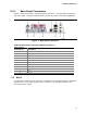
2.2.1 Back Panel Connectors
Figure 7 shows the location of the back panel connectors. The back panel connectors
are color-coded. The figure legend (Table 10) lists the colors used (when applicable).
Figure 7. Back Panel Connectors
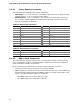
Table 10. Back Panel Connectors Shown in Figure 7
Item/callout
from Figure 7
Descri
ption
A PS/2 mouse port (Green)
B PS/2 keyboard port (Purple)
C Parallel port (Burgundy)
D Serial port A (Teal)
E VGA port
F S-Video output (optional)
G LAN
H USB ports [2]
I Line in
J Mic in
K Line out
NOTE
The back panel audio line out connector is designed to power headphones or amplified
speakers only. Poor audio quality occurs if passive (non-amplified) speakers are
connected to this output.