Intel® Core™ 2 Duo Mobile Processors on 45-nm process for Embedded Applications Thermal Design Guide June 2008 Order Number: 320028-001
INFORMATION IN THIS DOCUMENT IS PROVIDED IN CONNECTION WITH INTEL® PRODUCTS. EXCEPT AS PROVIDED IN INTEL’S TERMS AND CONDITIONS OF SALE FOR SUCH PRODUCTS, INTEL ASSUMES NO LIABILITY WHATSOEVER, AND INTEL DISCLAIMS ANY EXPRESS OR IMPLIED WARRANTY RELATING TO SALE AND/OR USE OF INTEL PRODUCTS, INCLUDING LIABILITY OR WARRANTIES RELATING TO FITNESS FOR A PARTICULAR PURPOSE, MERCHANTABILITY, OR INFRINGEMENT OF ANY PATENT, COPYRIGHT, OR OTHER INTELLECTUAL PROPERTY RIGHT.
Core™ 2 Duo Mobile Processors—Contents Contents 1.0 Introduction ............................................................................................................. 6 1.1 Design Flow ....................................................................................................... 6 1.2 Definition of Terms ............................................................................................. 7 1.3 Reference Documents....................................................................
Figures—Core™ 2 Duo Mobile Processors Figures 1 2 3 4 5 6 7 8 9 10 11 12 13 14 15 16 17 18 19 20 21 22 23 24 25 26 Thermal Design Process .............................................................................................. 7 Primary Side Keep Out Zone Requirements— Micro-FCPGA ............................................ 12 Primary Side Keep Out Zone Requirements— Micro-FCBGA ............................................ 13 Secondary Side Keep Out Zone Requirements ...............................
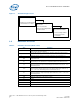
Core™ 2 Duo Mobile Processors—Tables Revision History Date Revision June 2008 1.0 Description First Public release.
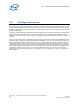
Introduction—Core™ 2 Duo Mobile Processors 1.0 Introduction The power dissipation of electronic components has risen along with the increase in complexity of computer systems. To ensure quality, reliability, and performance goals are met over the product’s life cycle, the heat generated by the device must be properly dissipated. Typical methods to improve heat dissipation include selective use of airflow ducting, and/or the use of heatsinks.
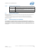
Core™ 2 Duo Mobile Processors—Introduction Figure 1. Thermal Design Process Step 1: Thermal Simulation • Package Level Thermal Models • Thermal Model User’s Guide Step 2: Heatsink Design and Selection • Reference Heatsinks • Reference Mounting Hardware • Vendor Contacts Step 3: Thermal Validation • Thermal Testing Software • Thermal Test Vehicle • User Guides 1.2 Definition of Terms Table 1. Definition of Terms (Sheet 1 of 2) Term Definition FCPGA Flip Chip Pin Grid Array.
Introduction—Core™ 2 Duo Mobile Processors Table 1. 1.3 Definition of Terms (Sheet 2 of 2) Term Definition TIM Thermal Interface Material – the thermally conductive compound between the heatsink and die. This material fills air gaps and voids, and enhances spreading of the heat from the die to the heatsink. U A unit of measure used to define server rack spacing height. 1U is equal to 1.75 inches, 2U equals 3.50 inches, etc.
Core™ 2 Duo Mobile Processors—Package Information 2.0 Package Information The Intel® Core™2 Duo Processor (XE and SV) is available in 478-pin Micro-FCPGA packages as well as 479-ball Micro-FCBGA packages. The Intel® Core™2 Duo Processor SFF processor (LV and ULV) is available in 956-ball Micro-FCBGA packages. The package mechanical dimensions can be found in the product’s datasheet. The Micro-FCBGA package incorporates land-side capacitors. The land-side capacitors are electrically conductive.
Thermal Specifications—Core™ 2 Duo Mobile Processors 3.0 Thermal Specifications 3.1 Thermal Design Power The Thermal Design Power (TDP) specification is listed in Table 2. Heat transfer through the microFCBGA, micro-FCPGA package and socket via the base board is negligible. The cooling capacity without a thermal solution is also minimal, so Intel requires the use of a heatsink for all usage conditions. 3.
Core™ 2 Duo Mobile Processors—Mechanical Specifications 4.0 Mechanical Specifications 4.1 Package Mechanical Requirements 4.1.1 Die Pressure/Load Upper Limit From a die mechanical integrity standpoint, the maximum allowable normal die load is the lesser of 15 lbs or 100 psi. Considering the 15 lbs load limit and the nominal die area of 1.45 cm2 (0.22 in.2), this equates to a die pressure of 66.7 psi (below 100 psi specification).
Mechanical Specifications—Core™ 2 Duo Mobile Processors Figure 2. Primary Side Keep Out Zone Requirements— Micro-FCPGA Notes: 1. Dimension in millimeters [inches].
Core™ 2 Duo Mobile Processors—Mechanical Specifications Figure 3. Primary Side Keep Out Zone Requirements— Micro-FCBGA Notes: 1. Dimension in millimeters [inches].
Mechanical Specifications—Core™ 2 Duo Mobile Processors Figure 4. Secondary Side Keep Out Zone Requirements Notes: 1. Dimension in millimeters [inches].
Core™ 2 Duo Mobile Processors—Thermal Solution Requirements 5.0 Thermal Solution Requirements 5.1 Thermal Solution Characterization The thermal characterization parameter, Ψ (“psi”), is used to characterize thermal solution performance, as well as compare thermal solutions in identical situations (i.e., heating source, local ambient conditions, etc.). It is defined by the following equation: Equation 1.
Thermal Solution Requirements—Core™ 2 Duo Mobile Processors Figure 5. Processor Thermal Characterization Parameter Relationships TA ΨSA HEATSINK TS TIM TJ ΨJA ΨTIM Device 5.1.1 Calculating the Required Thermal Performance for the Intel® Core™2 Duo processor Overall thermal performance, ΨJA, is then defined using the thermal characterization parameter: • Define a target component temperature TJUNCTION and corresponding TDP. • Define a target local ambient temperature, TA.
Core™ 2 Duo Mobile Processors—Thermal Solution Requirements It is evident from the above calculations that a reduction in the local ambient temperature can have a significant effect on the junction-to-ambient thermal resistance requirement. This effect can contribute to a more reasonable thermal solution including reduced cost, heatsink size, heatsink weight, or a lower system airflow rate.
Reference Thermal Solutions—Core™ 2 Duo Mobile Processors 6.0 Reference Thermal Solutions Intel has developed reference thermal solutions designed to meet the cooling needs of embedded form factor applications. This chapter describes the overall requirements for the reference thermal solution including critical-to-function dimensions, operating environment, and verification criteria.
Core™ 2 Duo Mobile Processors—Reference Thermal Solutions 6.2 Keep Out Zone Requirements The keep out zone requirements on the PCB to use this heatsink are detailed in Appendix B, “Mechanical Drawings”. Because it extends beyond the footprint of the device, it is critical for the board designer to allocate space on the board for the heatsink. 6.3 Thermal Performance The AdvancedTCA reference heatsink is an all copper (C1100) design.
Reference Thermal Solutions—Core™ 2 Duo Mobile Processors Figure 8. 1U Reference Heatsink Assembly 6.4.1 Keep Out Zone Requirements The keep out zone requirements on the PCB to use this heatsink are detailed in Appendix B, “Mechanical Drawings”. Because it extends beyond the footprint of the device, it is critical for board designers to allocate space for the heatsink. 6.4.
Core™ 2 Duo Mobile Processors—Reference Thermal Solutions Figure 9. 1U Heatsink Thermal Performance vs. Volumetric Airflow Rate 1U+ Reference Heatsink Performance 1.6 1.4 PSI (C/W) 1.2 1 0.8 0.6 0.4 Psi_ja 0.2 Psi_sa 0 0 5 10 15 20 25 30 Volum etric Air Flow Rate (CFM) 6.5 Compact PCI Reference Heatsink The cPCI reference thermal solution is shown in Figure 10. The maximum heatsink height is constrained to 8.7 mm. The heatsink uses the fastener assembly (refer to Section 6.
Reference Thermal Solutions—Core™ 2 Duo Mobile Processors 6.5.1 Keep Out Zone Requirements The keep out zone requirements on the PCB to use this heatsink are detailed in Appendix B, “Mechanical Drawings.” Because it extends beyond the footprint of the device, it is critical for board designers to allocate space for the heatsink. 6.5.2 Thermal Performance The cPCI reference heatsink is an all copper (C1100) design, intended for applications where vertical space is limited.
Core™ 2 Duo Mobile Processors—Reference Thermal Solutions Thermal interface materials have thermal impedance (resistance) that will increase as the material degrades over time. It is important for thermal solution designers to take this increase in impedance into consideration when designing a thermal solution. It is recommended that system integrators work with TIM suppliers to determine the performance of the desired thermal interface material.
Thermal Metrology—Core™ 2 Duo Mobile Processors 7.0 Thermal Metrology The system designer must make temperature measurements to accurately determine the performance of the thermal solution. Validation of the processor’s thermal solution should be done using a thermal test vehicle (TTV). The TTV allows for an accurate junction temperature measurement as well as input power control. For more information, contact your Intel field sales representative.
Core™ 2 Duo Mobile Processors—Thermal Metrology It is worthwhile to determine the local ambient temperature in the chassis around the processor to understand the effect it may have on the case temperature. TLA is best measured by averaging temperature measurements at multiple locations in the heatsink inlet airflow. This method helps reduce error and eliminate minor spatial variations in temperature.
Thermal Metrology—Core™ 2 Duo Mobile Processors Figure 13. Measuring TLA with an Active Heatsink Note: Drawing not to scale.
Core™ 2 Duo Mobile Processors—Thermal Metrology Figure 14. Measuring TLA with a Passive Heatsink Note: Drawing not to scale.
Reliability Guidelines—Core™ 2 Duo Mobile Processors 8.0 Reliability Guidelines Each motherboard, heatsink, and attach combination may vary the mechanical loading of the component. The user should carefully evaluate the reliability of the completed assembly prior to use in high volume. Some general recommendations are shown in Table 4. Table 4.
Core™ 2 Duo Mobile Processors—Thermal Solution Component Suppliers Appendix A Thermal Solution Component Suppliers These vendors and devices are listed by Intel as a convenience to Intel’s general customer base. Intel does not make any representations or warranties whatsoever regarding quality, reliability, functionality, or compatibility of these devices. This list and/or these devices may be subject to change without notice. Note: The enabled components may not be currently available from all suppliers.
Mechanical Drawings—Core™ 2 Duo Mobile Processors Appendix B Mechanical Drawings Table 6 lists the mechanical drawings included in this appendix. Table 6.
Core™ 2 Duo Mobile Processors—Mechanical Drawings Figure 15.
Mechanical Drawings—Core™ 2 Duo Mobile Processors Figure 16.
Core™ 2 Duo Mobile Processors—Mechanical Drawings Figure 17.
Mechanical Drawings—Core™ 2 Duo Mobile Processors Figure 18.
Core™ 2 Duo Mobile Processors—Mechanical Drawings Figure 19.
Mechanical Drawings—Core™ 2 Duo Mobile Processors Figure 20.
Core™ 2 Duo Mobile Processors—Mechanical Drawings Figure 21.
Mechanical Drawings—Core™ 2 Duo Mobile Processors Figure 22.
Core™ 2 Duo Mobile Processors—Mechanical Drawings Figure 23.
Mechanical Drawings—Core™ 2 Duo Mobile Processors Figure 24.
Core™ 2 Duo Mobile Processors—Mechanical Drawings Figure 25.
Mechanical Drawings—Core™ 2 Duo Mobile Processors Figure 26.