
Specifications


Intel
®
64 and IA-32 Architectures Software Developer’s Manual Documentation Changes 243
Documentation Changes
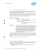
thermal monitor register and its associated interrupt were introduced in the Pentium 4
and Intel Xeon processors.
As shown in Figure 10-8, some of these fields and flags are not available (and reserved)
for some entries.
...
10.5.3 Error Handling
The local APIC provides an error status register (ESR) that it uses to record errors that it
detects when handling interrupts (see Figure 10-9). An APIC error interrupt is generated
Figure 10-8 Local Vector Table (LVT)
31 07
Vector
Timer Mode
0: One-shot
1: Periodic
1215161718
Delivery Mode
000: Fixed
100: NMI
Mask
†
0: Not Masked
1: Masked
Address: FEE0 0350H
Value After Reset: 0001 0000H
Reserved
12131516
Vector
31 07810
Address: FEE0 0360H
Address: FEE0 0370H
Vector
Vector
Error
LINT1
LINT0
Value after Reset: 0001 0000H
Address: FEE0 0320H
111: ExtlNT
All other combinations
are Reserved
Interrupt Input
Pin Polarity
Trigger Mode
0: Edge
1: Level
Remote
IRR
Delivery Status
0: Idle
1: Send Pending
Timer
13 11 8
11
14
17
Address: FEE0 0340H
Performance
Vector
Thermal
Vector
Mon. Counters
Sensor
Address: FEE0 0330H
† (Pentium 4 and Intel Xeon processors.) When a
performance monitoring counters interrupt is generated,
the mask bit for its associated LVT entry is set.
010: SMI
101: INIT