XP-P4I533E Intel® Pentium ® 4 Processor Motherboard User's Manual M-040602
Copyright Declaration © 2004 Gigatrend Technology Co., Ltd. All rights reserved. No part of this manual may be reproduced, copied, translated, or transmitted in any form or by any means without express permission from Gigatrend Technology. Companies and product names mentioned in this document are trademarks or registered trademarks of their respective owners.
Contents Motherboard Layout ........................................................................ 4 1. 5 Production Introduction ............................................................... 1.1. 1.2. Feature Summary ............................................................................. 5 I/O Back Panel and Connectors&Jumper Setting ............................. 6 1.2.1. I/O Back Panel .............................................................................. 6 1.2.2.
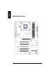
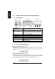
LAN CPU_FAN ATX COMA ATX_12V COMB LPT SOCKET 478 F_AUDIO Intel 845E XP-P4I533E CD_IN AGP DDR3 DDR1 FDD DDR2 USB KB_MS MIC_IN LINE_OUT LINE_IN GAME English Motherboard Layout BAT PCI1 CODEC CLR_CMOS PCI2 PCI3 Intel ICH4 SYS_FAN RTL8100C PCI4 IDE2 SMSC PCI5 BIOS F_USB1 IDE1 PWR_LED F_PANEL 4
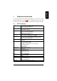
English 1. Production Introduction The user manual provides steps related to quick installation. If you wish to view complete product information, please select the " ",Open User Manual button located on the driver CD or link to our website at http://www.axper.com to received the most up-to-date information. 1.1.
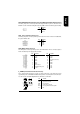
English 1.2. I/O Back Panel and Connectors&Jumper Setting 1.2.1. I/O Back Panel PS/2 Mouse LAN USB PS/2 Keyboard PS/2 Keyboard PS/2 Mouse connector USB (Universal Serial Bus Port) LAN (RJ45 LAN Port) Parallel port (LPT) COMA/COMB (Serial port) LineOut Line In Mic In 1.2.2. Parallel Port COM A Game Port COMB Line Out MIC In Connects PS/2 standard keyboard and PS/2 standard mouse Prior to use, please make sure that your system as well as the connected attachments support the USB interface.
The CPU_Fan power connector provides the largest amount of power to the CPU fan at 600mA. You can connect the casing fan to the SYS_FAN connector to enhance system cooling. PIN 1 2 3 1 SIGNAL GND +12V Sense ATX_12V (+12V Power Connector) The ATX_12V power connector provides power to the CPU. If this connector is not Attached, the system will not start. 3 4 1 2 PIN 1 2 3 4 SIGNAL GND GND +12V +12V ATX (ATX Power Connector) The ATX power connector provides power to the motherboard.
English PWR_LED Connects to the system power LED indicator whereby the power is indicated as ON or OFF. However, the indicator will flash when the system is suspended. PIN 1 2 3 1 SIGNAL MPD+ MPDMPD- CLR_CMOS (Clear CMOS) You can clear the motherboard CMOS with the jumper to return your system to its initial status. To prevent improper usage, the jumper does not include the jumper plug. If you wish to use the Clear CMOS function, please short circuit the 1-2Pin.
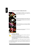
+ 2. The improper removal of the battery can result in harm. When replacing a battery, please make sure you use one that is of similar brand and model number. For information related to battery specifications and precautions, please refer to the manufacturer instructions. If you wish to delete the data stored in the CMOS, please follow the steps below: 1. Please turn off your computer and unplug the power. 2. Remove the battery from the motherboard. 3.
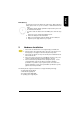
English 2.1. Installation of a Pentium 4 CPU and Fan Sink 1 Note the small gold colored triangle on one corner of the CPU. Place the triangle in the corner closest to the metal lever and gently insert the CPU into its position. 2 When the CPU is inserted into its position, gently press the metal lever downwards until a click is heard. Then add an even layer of heat sink paste between the CPU and fan sink for heat dissipation.
2. Once the memory module is correctly inserted, the clips will automatically refasten. If the memory mod ule is positioned in the wrong direction, it will not insert. If this occurs, please switch directions. 2.3. Installation of the Graphics Card 1. Before installing the graphics card, please carefully read the accompanying user manual. As well, make sure the computer power is turned off. 2. When installing or removing the graphics card, first pull out the white AGU knob before insertion or removal.
English
English 3. BIOS Setup BIOS (Basic Input and Output System) stores all the information of the motherboard settings that is needed for system initiation within the CMOS. The CMOS SETUP utility allows the user to make changes in BIOS configurations that are required or to activate certain features. The CMOS SETUP saves each item configuration in the CMOS SRAM of the motherboard. When the power is turned off, the battery on the motherboard supplies the required power to the CMOS SRAM.
English Gives the list of options available for each item Return to Optimized default values (not applicable to main setup screen) Enters Expert-Flash feature Displays system information Saves settings and exits setup 3.2. Standard CMOS Features ø Includes the settings for items such as date, time, floppy disk drive specifications, and hard drives connected to the IDE interface.
English n Floppy 3 Mode Support Allows user to configure a Japanese standard 3 Mode floppy drive. Options: Disabled (No 3 Mode drive installed) Drive A (3 Mode Drive installed in A:) Drive B (3 Mode Drive installed in B:) Both (3 Mode Drive installed in A: and B:) n Halt on Tells the BIOS specifically which types of errors will halt the computer during the poweron self test (POST) section of the boot.
English 3.3. ø Advanced BIOS Features Allows the configuration of advanced settings such as boot sequence, password check, etc.
ø English 3.4. Integrated Peripherals This menu allows you to control the various ports of the computer such as IDE, SATA, USB, IEEE1394, COM port, LPT port, AC97 audio, etc.
English n USB Mouse Support Allows user to use a USB-based mouse (Enable if you are using a USB mouse, otherwise Disable) (default:Disabled) n AC97 Audio Allows the user to use the onboard AC97 audio (default:Auto) n Onboard H/W LAN Allows the user to enable or disable the onboard LAN (default:Enabled) n Onboard LAN Boot ROM Allows user to enable or disable booting from a network drive.
English n Game Port Address Allows the user to select the Game Port Address Options: 201, 209, Disabled (default:201) n Midi Port Address Allows the user to select the Midi Port Address Options: 300, 330, 290, Disabled (default:Disabled) n Midi Port IRQ This feature can be configured when "Midi Port Address" is not disabled.
ø English 3.5. Power Management Setup This is used to control the various power saving features of the PC.
English n ModemRingOn To use this feature, an Ethernet card supporting the PCI2.2 or newer standard must be used. (default:Enabled) n Resume by Alarm If set to Enabled, the user can set the date and time for automatic system power-on. (default:Disabled) Settings: Date (of Month) Alarm : Everyday, 1~31 Time (hh: mm: ss) Alarm : (0~23) : (0~59) : (0~59) n POWER ON Function Allows the use of the mouse or keyboard to power system. Options: Disabled , Any Key , Mouse , Mouse/AnyKey(default:Disabled) 3.6.
ø English 3.7. PC Health Status This menu displays the current CPU temperature, the fan speeds, voltages etc. CMOS Setup Utility-Copyright (C) 1984-2004 Award Software PC Health Status Current CPU Temperature 45°C Item Help Current SYSTEM Temperature 30°C Menu Level} Vcore 1.78V +3.3V 3.36V +5V 5.14V +12V 11.84V +1.8V 1.
English 3.8. ø Frequency/Voltage Control This allows user to configure CPU frequency and voltage settings.
This feature can be configured when the "CPU Host Frequency" is set to Enabled and allows the user to adjust the PCI/AGP Frequency without affecting the CPU Frequency. n Host/DRAM Clock Ratio Allows the user to set the Host/DRAM Clock Ratio. If the FSB(Front Side Bus) is at 400MHz. 2.66 Memory Frequency = Host clock x 2.66. Auto Automatically sets memory frequency. (default:Auto) If the FSB(Front Side Bus) is at 533MHz. 2.0 Memory Frequency = Host clock x 2.0. 2.5 Memory Frequency = Host clock x 2.5.
English 3.9. ø "Top Performance" allows faster system start. However, the result may differ depending on system specifications (includes hardware and OS). For example, certain hardware may become unstable under Windows XP but work reliably under the Windows NT operating system. Thus, select Disabled under "Top Performance" if system hardware is affected. 3.10. ø 25 Save & Exit Setup To save any changes you made to the BIOS you must choose this option.
English 4. Driver Installation Driver installation for the Windows 98/98SE/200/ME/XP operating systems is simple. Once you insert the provided driver disks into your optical drive, the AUTORUN screen will appear. If this screen does not appear, you can use "D:\setup.exe" (with "D" being the specified drive) to bring up the screen shown below. Just follow the screen instructions to easily complete driver installation.