Intel® Server Board SE7320VP2 User Guide Order Number: C71354-002
Disclaimer Information in this document is provided in connection with Intel® products. No license, express or implied, by estoppel or otherwise, to any intellectual property rights is granted by this document.
Preface About this Manual ® Thank you for purchasing and using the Intel Server Board SE7320VP2. This manual is written for system technicians who are responsible for troubleshooting, upgrading, and reparing this server board. This document provides a brief overview of the features of the board/chassis, a list of accessories or other components you may need, troubleshooting information, and instructions on how to add and replace components on the Intel Server Board SE7320VP2.
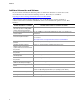
Preface Additional Information and Software If you need more information about this product or information about the accessories that can be used with this server board, use the following resources. These files are available at http://support.intel.com/support/motherboards/server/SE7320VP2 Unless otherwise indicated in the table below, once on this Web page, type the document or software name in the search field at the left side of the screen and select the option to search “This Product.
Preface Safety Information WARNING Before working with your server product, whether you are using this guide or any other resource as a reference, pay close attention to the safety instructions. You must adhere to the assembly instructions in this guide to ensure and maintain compliance with existing product certifications and approvals. Use only the described, regulated components specified in this guide.
Preface Warnings System power on/off: The power button DOES NOT turn off the system AC power. To remove power from system, you must unplug the AC power cord from the wall outlet. Make sure the AC power cord is unplugged before you open the chassis, add, or remove any components. Hazardous conditions, devices and cables: Hazardous electrical conditions may be present on power, telephone, and communication cables.
Preface Safety Cautions Read all caution and safety statements in this document before performing any of the instructions. See also Intel Server Boards and Server Chassis Safety Information on the Resource CD and/or at http://support.intel.com/support/motherboards/server/. SAFETY STEPS: Whenever you remove the chassis covers to access the inside of the system, follow these steps: 1. Turn off all peripheral devices connected to the system. 2. Turn off the system by pressing the power button. 3.
Preface 重要安全指导 在执行任何指令之前,请阅读本文档中的所有注意事项及安全声明。参见 Resource CD(资源光盘) 和/或 http://support.intel.com/support/motherboards/server/ 上的 Intel Server Boards and Server Chassis Safety Information(《Intel 服务器主板与服务器机箱安全信息》)。 Consignes de sécurité Lisez attention toutes les consignes de sécurité et les mises en garde indiquées dans ce document avant de suivre toute instruction. Consultez Intel Server Boards and Server Chassis Safety Information sur le CD Resource CD ou bien rendez-vous sur le site http://support.intel.
Preface Instrucciones de seguridad importantes Lea todas las declaraciones de seguridad y precaución de este documento antes de realizar cualquiera de las instrucciones. Vea Intel Server Boards and Server Chassis Safety Information en el CD Resource y/o en http://support.intel.com/support/motherboards/server/. INSTRUCCIONES DE SEGURIDAD: Cuando extraiga la tapa del chasis para acceder al interior del sistema, siga las siguientes instrucciones: 1.
Preface x
Contents Contents 1 Server Board Features................................................................................. 15 Connector and Header Locations ......................................................................................... 17 Configuration Jumpers .......................................................................................................... 18 Back Panel Connectors.........................................................................................................
Contents Characters Are Distorted or Incorrect........................................................................... 43 System Cooling Fans Do Not Rotate Properly ............................................................. 44 Diskette Drive Activity Light Does Not Light ................................................................. 44 CD-ROM Drive or DVD-ROM Drive Activity Light Does Not Light ............................... 45 Cannot Connect to a Server...........................................
Contents Tables Table 1. Table 2. Table 3. Table 4. Table 5. Table 6. Table 7. Table 8. Table 9. Table 10. Table 11. Server Board Features .................................................................................. 16 Recovery Jumper [J1H2, J1H3, J1H5] .......................................................... 18 Serial Port Configuration Jumper [J8A3] ....................................................... 19 BIOS Select Jumper [J1A4]................................................................
Contents xiv
1 Server Board Features This chapter briefly describes the main features of Intel® Server Board SE7320VP2. This chapter provides a photograph of the product, a list of the server board features, and diagrams showing the location of important components and connections on the server board. The Server Board SE7320VP2 is shown in the following picture. Figure 1.
Server Board Features Table 1 summarizes the major features of the server board. Table 1. Server Board Features Feature Description Processors Support for up to two Intel® Xeon™ processors with an 800 MT/s MHz front side bus and frequencies starting at 2.8 GHz.
Server Board Features Connector and Header Locations A BC D E CC BB F AA G Z Y X W V U H T S R Q P N O M I J L K TP00941 A Serial Port A header B Battery C D E F G Full-height PCI slot Low-profile PCI slot Back panel I/O ports Serial port selection jumper DIMM sockets H Processor 1 fan header I Processor 1 socket J Processor 2 socket K Processor 2 fan header L +12V processor power connector M Fan board connector N Floppy connector O PCI fan connecors (two) P IDE connector Q 100-pin Flopp
Server Board Features Configuration Jumpers Recovery Jumpers J1H2, J1H3, J1H5 J1H2 Pass Clr 3 2 Protect Erase J1H3 Rcvr Boot 2 3 Recovery Boot Normal Boot J1H5 CMOS Clr 3 2 BMC Control Force Erase TP00942 Figure 3. Recovery Jumper Location Table 2. Recovery Jumper [J1H2, J1H3, J1H5] Jumper Name Pins What happens at system reset… J1H2: Password Clear 1-2 If these pins are jumpered, administrator and user passwords will be cleared on the next reset.
Server Board Features Serial Port Configuration Jumper J8A3 3 4 1-3: DCD to DTR (Default) 2-4: DSR to DTR 2 TP00944 Figure 4. Serial Port Configuration Jumper Location Table 3. Serial Port Configuration Jumper [J8A3] Pins What happens at system reset… 1-3 Serial port is configured for DCD to DTR (default) 2-4 Serial port is configured for DSR to DTR.
Server Board Features BIOS Select Jumper J1A4 BIOS Select 1-2: Normal Operation (Default) 3 3 2-3: Force to Lower Bank TP00949 Figure 5. BIOS Select Jumper Location Table 4.
Server Board Features Back Panel Connectors A B C D E F G H TP00943 A B C D Mouse Keyboard Serial Port B NIC1 (1 Gb) E F G H NIC2 (1 Gb) Video USB1 USB2 Figure 6. Back Panel Connectors The NIC LEDs at the right and left of each NIC provide the following information. Table 5.
Server Board Features Hardware Requirements To avoid integration difficulties and possible board damage, your system must meet the requirements outlined below. For a list of qualified components, see the links under “Additional Information and Software.” Processor One or two Intel® Xeon™ processors with an 800MHz front side bus and a minimum of 2.8 GHz frequency must be installed. The following table outlines the supported processors.
Server Board Features DIMMs must meet the following requirements: Use only DDR266 or DDR33, registered DDR DIMM modules Use only DIMMs that comply with the DDR specifications. DDR266 and DDR333 memory can be mixed on the server board, but when mixing DIMM types, DDR333 memory will be treated as DDR266. Use only DIMMs with DIMM organization of x72 ECC Use only 184-pin DIMMs Use only DIMMs with the capacities outlined in the following table Table 7.
Server Board Features For memory on-line sparing, one DIMM per channel is used as the memory spare. The spare DIMM is not available for use, but is kept in reserve. If a DIMM begins to fail, the content of the failing DIMM is copied to the spare DIMM in that channel. When all of the data is copied to the spare DIMM, the primary DIMM is removed from service and the spare DIMM takes its place.
2 Hardware Installations and Upgrades Before You Begin Before working with your server product, pay close attention to the Safety Information at the beginning of this manual.
Hardware Installations and Upgrades 4. Remove the server’s cover. See the documentation that accompanied your server chassis for instructions on removing the server’s cover. 5. Locate the DIMM sockets (see Figure 7). DIMM 2A DIMM 3B DIMM 3A DIMM 2B DIMM 1A DIMM 1B TP00761 Figure 7. Installing Memory 6. Make sure the clips at either end of the DIMM socket(s) are pushed outward to the open position. 7. Holding the DIMM by the edges, remove it from its anti-static package. 8.
Hardware Installations and Upgrades Removing DIMMs To remove a DIMM, follow these steps: 1. Observe the safety and ESD precautions at the beginning of this book. 2. Turn off all peripheral devices connected to the server. Turn off the server. 3. Remove the AC power cord from the server. 4. Remove the server’s cover. See the documentation that accompanied your server chassis for instructions on removing the server’s cover. 5. Gently spread the retaining clips at each end of the socket.
Hardware Installations and Upgrades Installing or Replacing the Processor CAUTIONS Processor must be appropriate: You may damage the server board if you install a processor that is inappropriate for your server. See “Additional Information and Software” for a link to the list of compatible processor(s). ESD and handling processors: Reduce the risk of electrostatic discharge (ESD) damage to the processor by doing the following: (1) Touch the metal chassis before touching the processor or server board.
Hardware Installations and Upgrades 6. Align the pins of the processor with the socket, and insert the processor into the socket. ✏ NOTE Make sure the alignment triangle mark and the alignment triangle cutout align correctly. A B A TP00764 Figure 9. Inserting Processor 7. Lower the socket lever completely. TP00765 Figure 10.
Hardware Installations and Upgrades Installing the Heat Sink(s) 1. The heat sink has Thermal Interface Material (TIM) located on the bottom of it. Use caution when you unpack the heat sink so you do not damage the TIM. 2. Set the heat sink over the processor, lining up the four captive screws with the four posts surrounding the processor. 3. Loosely screw in the captive screws on the heat sink corners in a diagonal manner (screw in one screw, then the screw located diagonally to the first screw).
Hardware Installations and Upgrades 8. Lift the heat sink from the processor. If it does not pull up easily, twist the heat sink again. Do not force the heat sink from the processor. Doing so could damage the processor. 9. Lift the processor lever. 10. Remove the processor. 11. If installing a replacement processor, see “Installing the Processor.” Otherwise, reinstall the chassis cover.
Hardware Installations and Upgrades Installing a PCI, PCI-X, or PCI-Express* Add-in Card Add-in cards are not included with your system and must be purchased separately. This server board requires the use of a riser bracket assembly with one or more riser connectors installed on it in order to use a PCI, PCI-X, or PCI-Express add-in card. The riser assembly is typically included with your server chassis. You may need to order the riser connector(s) separately, depending on the server chassis.
Hardware Installations and Upgrades VAROITUS Paristo voi räjähtää, jos se on virheellisesti asennettu. Vaihda paristo ainoastaan laitevalmistajan suosittelemaan tyyppiin. Hävitä käytetty paristo valmistajan ohjeiden mukaisesti. 1. 2. 3. 4. Observe the safety and ESD precautions at the beginning of this book. Turn off all peripheral devices connected to the server. Turn off the server. Disconnect the AC power cord from the server. Remove the server’s cover and locate the battery.
3 Server Utilities Using the BIOS Setup Utility This section describes the BIOS Setup Utility options, which is used to change server configuration defaults. You can run BIOS Setup with or without an operating system being present. See “Additional Information and Software” for a link to the Technical Product Specification where you will find details about specific BIOS setup screens.
Server Utilities Table 8. Keyboard Commands Press Description Help - Pressing F1 on any menu invokes the general Help window. The left and right arrow keys are used to move between the major menu pages. The keys have no affect if a submenu or pick list is displayed. Select Item up - The up arrow is used to select the previous value in a menu item’s option list, or a value field pick list. Pressing the Enter key activates the selected item.
Server Utilities Upgrading the BIOS The upgrade utility allows you to upgrade the BIOS in flash memory. The code and data in the upgrade file include the following: On-board system BIOS, including the recovery code, BIOS Setup Utility, and strings. On-board video BIOS and other option ROMs for devices embedded on the server board.
Server Utilities Upgrading the BIOS Follow the instructions in the readme file that came with the BIOS upgrade. When the update completes, remove the bootable media from which you performed the upgrade. ✏ NOTES Do not power down the system during the BIOS update process! The system will reset automatically when the BIOS update process is completed. You may encounter a CMOS Checksum error or other problem after reboot. If this happens, shut down the system and boot it again.
Server Utilities 4. Reconnect the AC power, power up the system. 5. Power down the system and disconnect the AC power. 6. Return the Password Clear jumper to the Password Clear Protect position, covering pins 2 and 3. 7. Close the server chassis. 8. Reconnect the AC power and power up the server. Clearing the CMOS If you are not able to access the BIOS setup screens, the CMOS Clear jumper will need to be used to reset the configuration RAM. The CMOS Clear jumper is located on jumper block J1H5. 1.
4 Troubleshooting This chapter helps you identify and solve problems that might occur while you are using the system. For any issue, first ensure you are using the latest firmware and files. Firmware upgrades include updates for BIOS, the baseboard management controller (BMC), and the hot-swap controller (HSC). See “Additional Information and Software” for a link to the software updates.
Troubleshooting Problems following Initial System Installation Problems that occur at initial system startup are usually caused by an incorrect installation or configuration. Hardware failure is a less frequent cause. If the problem you are experiencing is with a specific software application, see “Problems with Newly Installed Application Software.
Troubleshooting Hardware Diagnostic Testing This section provides a more detailed approach to identifying a hardware problem and locating its source. CAUTION Turn off devices before disconnecting cables: Before disconnecting any peripheral cables from the system, turn off the system and any external peripheral devices. Failure to do so can cause permanent damage to the system and/or the peripheral devices. 1. Turn off the system and all external peripheral devices.
Troubleshooting Specific Problems and Corrective Actions This section provides possible solutions for these specific problems: Power light does not light. No characters appear on screen. Characters on the screen appear distorted or incorrect. System cooling fans do not rotate. Diskette drive activity light does not light. Hard disk drive activity light does not light. CD-ROM drive activity light does not light. There are problems with application software.
Troubleshooting No Characters Appear on Screen Check the following: Is the keyboard functioning? Test it by turning the “Num Lock” function on and off to make sure the Num Lock light is functioning.
Troubleshooting System Cooling Fans Do Not Rotate Properly If the system cooling fans are not operating properly, it is an indication of possible system component failure. Check the following: Is the power-on light lit? If not, see “Power Light Does Not Light” If your system has LED lights for the fans, is one or more of these LEDs lit? Are any other front panel LEDs lit? Have any of the fan motors stopped? Use the server management subsystem to check the fan status.
Troubleshooting CD-ROM Drive or DVD-ROM Drive Activity Light Does Not Light Check the following: Are the CD-ROM/DVD-ROM drive’s power and signal cables properly installed? Are all relevant switches and jumpers on the drive set correctly? Is the drive properly configured? Cannot Connect to a Server Make sure the network cable is securely attached to the correct connector at the system back panel. Try a different network cable. Make sure you are using the correct and the current drivers.
Troubleshooting The add-in adapter stopped working without apparent cause. Try reseating the adapter first; then try a different slot if necessary. The network driver files may be corrupt or deleted. Delete and then reinstall the drivers. Run the diagnostics. System Boots when Installing PCI Card System Server Management features require full-time “standby” power.
Troubleshooting If you suspect that a transient voltage spike, power outage, or brownout might have occurred, reload the software and try running it again. Symptoms of voltage spikes include a flickering video display, unexpected system reboots, and the system not responding to user commands. ✏ NOTE Random errors in data files: If you are getting random errors in your data files, they may be getting corrupted by voltage spikes on your power line.
Troubleshooting LED Information ® The Intel Server Board SE7320VP2 includes LEDs that can aid in troubleshooting your system. A table of these LEDs with a description of their use is listed below. Table 9. Keyboard Commands LED Name Function Location Color Correction ID Aid in server identification from the back panel Control panel and board rear left corner Blue Press ID LED button or user Server Management software to turn off the LED.
Regulatory and Compliance Information Product Regulatory Compliance Product Safety Compliance The Server Board SE7320VP2-E complies with the following safety requirements: UL60950 – CSA 60950(USA / Canada) EN60950 (Europe) IEC60950 (International) CB Certificate & Report, IEC60950 (report to include all country national deviations) GOST R 50377-92 – Listed on one System License (Russia) Belarus License – Listed on System License (Belarus) CE - Low Voltage Directive 73/23/EEE (Europe) IRAM Ce
Regulatory and Compliance Information Certifications / Registrations / Declarations UL Certification (US/Canada) CE Declaration of Conformity (CENELEC Europe) FCC/ICES-003 Class A Attestation (USA/Canada) C-Tick Declaration of Conformity (Australia) MED Declaration of Conformity (New Zealand) BSMI Certification (Taiwan) GOST – Listed on one System License (Russia) Belarus – Listed on one System License (Belarus) RRL Certification (Korea) Ecology Declaration (International) Product Reg
Regulatory and Compliance Information Electromagnetic Compatibility Notices FCC (USA) This device complies with Part 15 of the FCC Rules. Operation is subject to the following two conditions: (1) this device may not cause harmful interference, and (2) this device must accept any interference received, including interference that may cause undesired operation. For questions related to the EMC performance of this product, contact: Intel Corporation 5200 N.E.
Regulatory and Compliance Information Industry Canada (ICES-003) Cet appareil numérique respecte les limites bruits radioélectriques applicables aux appareils numériques de Classe A prescrites dans la norme sur le matériel brouilleur: “Apparelis Numériques”, NMB-003 édictee par le Ministre Canadian des Communications.
Getting Help World Wide Web http://support.intel.com/support/motherboards/server/SE7320VP2 Telephone All calls are billed US $25.00 per incident, levied in local currency at the applicable credit card exchange rate plus applicable taxes. (Intel reserves the right to change the pricing for telephone support at any time without notice). Before calling, fill out an “Intel® Server Issue Report Form.” A sample form is provided on the following pages.
Getting Help In Latin America Brazil Mexico 001-916 377 0180 Contact AT&T USA at 001 800 462 628 4240. Once connected, dial 800 843 4481 Colombia Contact AT&T USA at 01 800 911 0010. Once connected, dial 800 843 4481 Costa Rica Contact AT&T USA at 0 800 0 114 114. Once connected, dial 800 843 4481 Panama Contact AT&T USA at 00 800 001 0109. Once connected, dial 800 843 4481 Chile (Easter Island) Contact AT&T U SA at 800 800 311.
® Intel Server Issue Report Form ✏ NOTE An on-line / automatic submission version of this form is available at http://support.intel.com/support/motherboards/server/SE7320VP2. For the fastest service, please submit your form via the Internet. Date Submitted: Company Name: Contact Name: Email Address: Intel Server Product: Priority (Critical, Hot, High, Low): Brief Problem Description. Provide a brief description below. See the last page for space to include a detailed problem description.
Issue Report Form Operating System Information Operating System Version Service Pack Peripheral Information Check each box below that is used, and provide the requested information Peripheral Card or Peripheral Description Low-profile Riser Top slot Center slot Bottom slot Full-height Riser Top slot Center slot Bottom slot Video On-Board Video Add-in Video NIC On-Board NIC1 (10/100/1000 Mb) On-Board NIC2 (10/100/1000 Mb) Hard Drive Information: ATA # of drives ins
Complete Problem Description In the space below, provide a complete description of the steps used to reproduce the problem or a complete description of where the problem can be found. Please also include any details on troubleshooting already done.