Intel® Entry Server Board SE7210TP1-E User Guide Order Number: C49109-002
Disclaimers Disclaimer Information in this document is provided in connection with Intel® products. No license, express or implied, by estoppel or otherwise, to any intellectual property rights is granted by this document.
Preface Preface About this Manual ® Thank you for purchasing and using the Intel Entry Server Board SE7210TP1-E. This manual is written for system technicians who are responsible for troubleshooting, upgrading, and repairing this server board. This document provides a brief overview of the features of the board/chassis, a list of accessories or other components you may need, troubleshooting information, and instructions on how to add and replace components on the Intel Entry Server Board SE7210TP1-E.
Preface Additional Information and Software If you need more information about this product or information about the accessories that can be used with this server board, go to this link to find the information below: http://www.support.intel.com/support/motherboards/server/SE7210TP1-E/index.htm In-depth technical information about this product, including BIOS settings and chipset ® information in the Intel Server Board SE7210TP1-E Technical Product Specification.
Safety Information Safety Information Before working with your server product, whether you are using this guide or any other resource as a reference, pay close attention to the safety instructions. Emissions Disclaimer To ensure EMC compliance with your local regional rules and regulations, the final configuration of your end system product may require additional EMC compliance testing. For more information please contact your local Intel Representative. See “Error! Hyperlink reference not valid.
Safety Information Installing or removing jumpers: A jumper is a small plastic encased conductor that slips over two jumper pins. Some jumpers have a small tab on top that you can grip with your fingertips or with a pair of fine needle nosed pliers. If your jumpers do not have such a tab, take care when using needle nosed pliers to remove or install a jumper; grip the narrow sides of the jumper with the pliers, never the wide sides.
Contents Contents Warnings ......................................................................................................... v 1 Server Board Features................................................................................. 11 Server Board Connector and Component Locations ............................................................ 13 Internal Component Connections.......................................................................................... 14 Configuration Jumpers ..........
Contents CD-ROM Drive or DVD-ROM Drive Activity Light Does Not Light ............................... 36 Cannot Connect to a Server......................................................................................... 37 Problems with Network................................................................................................. 37 System Boots when Installing PCI Card....................................................................... 38 Problems with Newly Installed Application Software....
Contents Figures ® Figure 1. Intel Server Board SE7210TP1-E......................................................................... 11 Figure 2. Intel Server Board SE7210TP1-E Layout .............................................................. 13 Figure 3. Making Connections to the Server Board .............................................................. 14 Figure 4. Configuration Jumper Location .............................................................................. 15 Figure 5.
Contents x
Server Board Features 1 Server Board Features This chapter briefly describes the main features of Intel® Server Board SE7210TP1-E. This chapter provides a photograph of the product, a list of the server board features, and diagrams showing the location of important components and connections on the server board. This server board is available in two options: The server board SE7210TP1 includes dual-channel Serial ATA, and dual-channel Parallel ATA support.
Server Board Features Table 1 summarizes the major features of the server board. Table 1.
Server Board Features Server Board Features (continued) Power Management Support for ACPI: Suspend to RAM (STR) Wake on USB, PCI, RS-232, PS/2, LAN, and front panel Server Management Intel® Server Management 5.
Server Board Features Internal Component Connections The connections you make depend on the chassis you are installing the board into and the components you are installing. You may not need to make all of the connections shown in Figure 3. If your Server Board SE7210TP1-E is installed into the Server Chassis SC5250-E, make sure the hard drive cage is installed before making your connections. This is necessary because the hard drive cage contains one of the front system fans.
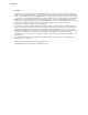
Server Board Features Configuration Jumpers J1D1 15 14 13 11 10 9 7 6 5 3 2 1 TP00630 Figure 4. Configuration Jumper Location Table 2. Configuration Jumper [J1D1] Jumper Name Pins What happens at system reset… CMOS clear 2-3 If these pins are jumpered, the CMOS settings will be cleared on the next reset. Password Clear 6-7 BIOS Flash Write Protect 11-12 BIOS Recovery 14-15 These pins should be jumpered on 1-2 for normal operation.
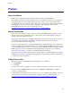
Server Board Features Back Panel Connectors A B C D E F TP00508 A. B. C. D. E. F. USB 1, 2, 3 Keyboard/mouse Serial port A Video NIC1 (1Gbit) NIC2 (10/100 Mbit) Figure 5. Back Panel Connectors The NIC LEDs at the right and left of each NIC provide the following information. Table 3.
Server Board Features Hardware Requirements To avoid integration difficulties and possible board damage, your system must meet the requirements outlined below. For a list of qualified components see the links under “Additional Information and Software.” Processor A minimum of one 2.0 GHz Intel Pentium 4 processor with 512KB cache support is required. For a complete list of supported processors, see the links under “Additional Information and Software.
Server Board Features 18 Intel Server Board SE7210TP1-E User Guide
Server Board Installations and Upgrades 2 Server Board Installations and Upgrades Before You Begin Before working with your server product, pay close attention to the Safety Information at the beginning of this manual.
Server Installations and Upgrades 2B 2A 1B 1A 1 3 2 1 3 TP00518 Figure 6. Installing Memory 5. Make sure the clips at either end of the DIMM socket(s) are pushed outward to the open position. 6. Holding the DIMM by the edges, remove it from its anti-static package. 7. Position the DIMM above the socket. Align the small notch in the bottom edge of the DIMM with the keys in the socket (see inset in Figure 6). 8. Insert the bottom edge of the DIMM into the socket. 9.
Server Board Installations and Upgrades Installing or Replacing the Processor NOTES Use the instructions provided below to install or replace a processor instead of using the instructions that came with the processor. CAUTIONS Processor must be appropriate: You may damage the server board if you install a processor that is inappropriate for your server. See “Additional Information and Software” for a link to the list of compatible processors.
Server Installations and Upgrades 5. If there is no thermal interface material on the bottom of the heat sink, use the enclosed syringe and apply the thermal interface material to the top of the processor. 6. Place the fan heat sink on top of the processor. TP00520 Figure 8. Attaching the Heat Sink to the Processor 7. Fully open the levers at the top of the heat sink, as shown by letter “A” in Figure 9. 8.
Server Board Installations and Upgrades 9. Firmly push the levers closed. It may be necessary to exert pressure to close the levers. See Figure 10. TP00522 Figure 10. Attaching the Fan Heat Sink Clips to the Processor Socket 10. Connect the processor fan cable to the processor fan connector. See Figure 11. TP00523 Figure 11.
Server Installations and Upgrades Removing the Processor To remove the processor, follow these instructions: 1. Observe the safety and ESD precautions at the beginning of this document. 2. Disconnect the processor fan cable. 3. Open the levers on the heat sink. 4. Disengage the retention mechanism hooks at the bottom of the heat sink. 5. Lift the heat sink from the processor. 6. Lift the processor lever. 7. Remove the processor.
Server Board Installations and Upgrades ADVARSEL Lithiumbatteri - Eksplosjonsfare. Ved utskifting benyttes kun batteri som anbefalt av apparatfabrikanten. Brukt batteri returneres apparatleverandøren. VARNING Explosionsfara vid felaktigt batteribyte. Använd samma batterityp eller en ekvivalent typ som rekommenderas av apparattillverkaren. Kassera använt batteri enligt fabrikantens instruktion. VAROITUS Paristo voi räjähtää, jos se on virheellisesti asennettu.
Server Installations and Upgrades 7. Dispose of the battery according to local ordinance. 8. Remove the new lithium battery from its package, and, being careful to observe the correct polarity, insert it in the battery socket. 9. Close the chassis. 10. Run Setup to restore the configuration settings to the RTC.
Server Utilities 3 Server Utilities BIOS Setup Table 4. Press Keyboard Commands Description Help - Pressing F1 on any menu invokes the general Help window. The left and right arrow keys are used to move between the major menu pages. The keys have no affect if a submenu or pick list is displayed. Select Item up - The up arrow is used to select the previous value in a menu item’s option list, or a value field pick list. Pressing the Enter key activates the selected item.
Server Utilities Upgrading the BIOS The upgrade utility allows you to upgrade the BIOS in flash memory.
Server Utilities Creating a Bootable Diskette Use a DOS system to create the diskette as follows: 1. Insert a diskette in diskette drive A. 2. At the C:\ prompt, for an unformatted diskette, type: format a:/s or, for a diskette that is already formatted, type: sys a: 4. Press . Creating the BIOS Upgrade Diskette The BIOS upgrade file is a compressed self-extracting archive that contains the files you need to upgrade the BIOS. 1. Insert the bootable diskette into the diskette drive. 2.
Server Utilities 10. If you do not set the CMOS values back to defaults using the F9 key, the system may function erratically. ✏ NOTE You may encounter a CMOS Checksum error or other problem after reboot. If this happens, shut down the system and boot it again. CMOS checksum errors require that you enter Setup, check your settings, save your settings, and exit Setup. Changing the BIOS Language You can use the BIOS upgrade utility to change the language the BIOS uses for messages and the Setup program.
Server Utilities 5. A blue screen will be displayed and the recovery process will automatically run. The system will continue to beep throughout the recovery process. The recovery process is complete when the beeping stops. 6. Remove the diskette. 7. Power down and unplug the system from the AC power source. 8. Move the BIOS recovery jumper at J1D1 back to the original position, covering pins 13 and 14. 9. Plug the system into the AC power source and power it up to confirm that the recovery was successful.
Troubleshooting 4 Troubleshooting This chapter helps you identify and solve problems that might occur while you are using the system. For any issue, first ensure you are using the latest firmware and files. Firmware upgrades include updates for BIOS, the mini baseboard management controller (mBMC), and the hot-swap controller (HSC). See “Additional Information and Software” for a link to the software updates.
Troubleshooting Are all peripheral devices installed correctly? If the system has a hard disk drive, is it properly formatted or configured? Are all device drivers properly installed? Are the configuration settings made in Setup correct? Is the operating system properly loaded? Refer to the operating system documentation.
Troubleshooting Confirming Loading of the Operating System Once the system boots up, the operating system prompt appears on the screen. The prompt varies according to the operating system. If the operating system prompt does not appear, see “No Characters Appear on Screen.” Specific Problems and Corrective Actions This section provides possible solutions for these specific problems: Power light does not light. No characters appear on screen. Characters on the screen appear distorted or incorrect.
Troubleshooting No Characters Appear on Screen Check the following: Is the keyboard functioning? Test it by turning the “Num Lock” function on and off to make sure the Num Lock light is functioning.
Troubleshooting System Cooling Fans Do Not Rotate Properly If the system cooling fans are not operating properly, it is an indication of possible system component failure. Check the following: Is the power-on light lit? If not, see “Power Light Does Not Light” If your system has LED lights for the fans, is one or more of these LEDs lit? Are any other front panel LEDs lit? Have any of the fan motors stopped? Use the server management subsystem to check the fan status.
Troubleshooting Cannot Connect to a Server Make sure the network cable is securely attached to the correct connector at the system back panel. Try a different network cable. Make sure you are using the correct and the current drivers. See “Additional Information and Software” for a link to the current drivers. Make sure the driver is loaded and the protocols are bound. Make sure the hub port is configured for the same duplex mode as the network controller.
Troubleshooting System Boots when Installing PCI Card System Server Management features require full-time “standby” power. This means some parts of the system have power going to them whenever the power cord is plugged in, even if you have turned the system power off with the power button on the front panel. If you install a PCI card with the AC power cord plugged in, a signal may be sent to the command the system to boot.
Troubleshooting ✏ NOTE Random errors in data files: If you are getting random errors in your data files, they may be getting corrupted by voltage spikes on your power line. If you are experiencing any of the above symptoms that might indicate voltage spikes on the power line, you may want to install a surge suppressor between the power outlet and the system power cord.
Troubleshooting LED Information ® The Intel Server Board SE7210TP1-E includes LEDs that can aid in troubleshooting your system. A table of these LEDs with a description of their use is listed below. LED Name Function Location Color Correction ID Aid in server identification from the back panel Front Panel and board rear left corner Blue Press ID LED button or user Server Management software to turn off the LED.
Troubleshooting BIOS Error Messages When a recoverable error occurs during the POST, the BIOS displays an error message describing the problem (see Table 5). Table 5. BIOS Error Messages Error Message Explanation GA20 Error An error occurred with Gate A20 when switching to protected mode during the memory test. Pri Master HDD Error Pri Slave HDD Error Sec Master HDD Error Sec Slave HDD Error Could not read sector from corresponding drive.
Troubleshooting BIOS Error Messages (continued) Error Message Explanation On Board Parity Error A parity error occurred in onboard memory. This error is followed by an address. Parity Error A parity error occurred in onboard memory at an unknown address. NVRAM / CMOS / PASSWORD cleared by Jumper NVRAM, CMOS, and passwords have been cleared. The system should be powered down and the jumper removed. Pressed CMOS is ignored and NVRAM is cleared. User must enter Setup.
Troubleshooting An error or warning condition at boot can result in a series of beeps being issued known as "beep ® codes. These beeps have a code that identifies system or PCI card events. For example, some Intel RAID cards have beep codes. Before checking for a system beep code error make sure the PCI card is not causing the beeping. In the case of a Bootblock update, where video is not available for text messages to be displayed, speaker beeps are necessary to inform the user of errors.
Regulatory and Compliance Information Regulatory and Compliance Information Product Regulatory Compliance Product Safety Compliance The Server Board SE7210TP1-E complies with the following safety requirements: UL 1950 - CSA 950 (US/Canada) EN 60 950 (European Union) IEC60 950 (International) CE – Low Voltage Directive (73/23/EEC) (European Union) EMKO-TSE (74-SEC) 207/94 (Nordics) GOST R 50377-92 (Russia) Product EMC Compliance The Server Board SE7210TP1-E has been has been tested and verified
Regulatory and Compliance Information Product Regulatory Compliance Markings This product is marked with the following Product Certification Markings: Table 8. Product Certification Markings UL Recognition Mark CE Mark Russian GOST Mark Australian C-Tick Mark BSMI DOC Marking BSMI EMC Warning RRL MIC Mark Electromagnetic Compatibility Notices FCC (USA) This device complies with Part 15 of the FCC Rules.
Regulatory and Compliance Information This equipment has been tested and found to comply with the limits for a Class A digital device, pursuant to Part 15 of the FCC Rules. These limits are designed to provide reasonable protection against harmful interference in a residential installation. This equipment generates, uses, and can radiate radio frequency energy and, if not installed and used in accordance with the instructions, may cause harmful interference to radio communications.
Regulatory and Compliance Information Korean RRL Compliance This product has been tested and complies with MIC Notices No. 1997-41 and 1997-42. The product has been marked with the MIC logo to illustrate compliance. The English translation for the above is as follows: 1. Type of Equipment (Model Name): SE7210TP1-E 2. Certification No.: Contact Intel Representative 3. Name of Certification Recipient: Intel 4. Date of Manufacturer: Marked on Product 5.
Getting Help Getting Help World Wide Web http://www.support.intel.com/support/motherboards/server/SE7210TP1-E Telephone All calls are billed US $25.00 per incident, levied in local currency at the applicable credit card exchange rate plus applicable taxes. (Intel reserves the right to change the pricing for telephone support at any time without notice). Before calling, fill out an “Intel® Server Issue Report Form.” A sample form is provided on the following pages.
Issue Report Form ® Intel Server Issue Report Form ✏ NOTE An on-line / automatic submission version of this form is available at http://www.support.intel.com/support/motherboards/server/SE7210TP1-E . For the fastest service, please submit your form via the Internet. Date Submitted: Company Name: Contact Name: Email Address: Intel Server Product: Priority (Critical, Hot, High, Low): Brief Problem Description. Provide a brief description below.
Issue Report Form Operating System Information Operating System Version Service Pack Peripheral Information Check each box below that is used, and provide the requested information Peripheral Card Or Peripheral Description Driver Revision IRQ # I/O Base Address FW Rev# P64 Segment B (PCI-X 64/66) PCI Slot 1 PCI Slot 2 PCI Slot 3 P32 Segment A (PCI 32/33) PCI Slot 6 Video On-Board Video Add-in Video NIC On-Board NIC1 (1.
Issue Report Form Complete Problem Description In the space below, provide a complete description of the steps used to reproduce the problem or a complete description of where the problem can be found. Please also include any details on troubleshooting already done.