USER’S MANUAL PMB-601LF Intel® Core 2 Duo ATX Motherboard With VGA/Sound/2LAN PMB-601LF M1
Copyright Notice PMB-601LF Intel® Core 2 Duo ATX Motherboard With VGA/ Sound/ 2LAN OPERATION MANUAL COPYRIGHT NOTICE This operation manual is meant to assist both Embedded Computer manufacturers and end users in installing and setting up the system. The information contained in this document is subject to change without any notice. This manual is copyrighted in January, 2007. You may not reproduce or transmit in any form or by any means, electronic, or mechanical, including photocopying and recording.
Copyright Notice FCC NOTICE This equipment has been tested and found to comply with the limits for a Class A digital device, pursuant to part 15 of the FCC Rules. These limits are designed to provide reasonable protection against harmful interference when the equipment is operated in a commercial environment. This equipment generates, uses, and can radiate radio frequency energy and, if not installed and used in accordance with the instruction manual, may cause harmful interference to radio communications.
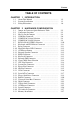
Contents TABLE OF CONTENTS CHAPTER 1-1 1-2 1-3 CHAPTER 2-1 2-2 2-3 2-4 2-5 2-6 2-7 2-8 2-9 2-10 2-11 2-12 2-13 2-14 2-15 2-16 2-17 2-18 2-19 2-20 2-21 2-22 2-23 2-24 2-25 2-26 2-27 2-28 2-29 2-30 2-31 1 INTRODUCTION About This Manual ........................................................ System Specification ...................................................... Safety Precautions .........................................................
Contents CHAPTER 3-1 3-2 3-3 3-4 3-5 3-6 3-7 3-8 CHAPTER 4-1 4-2 4-3 4-4 4-5 4-6 4-7 4-8 4-9 4-10 4-11 4-12 4-13 4-14 4-15 3 SOFTWARE UTILITIES Introduction …………..........................................…....... VGA Driver Utility ……………………………….…… Flash BIOS Update ..............................................…....... LAN Driver Utility …...........................................…...... Sound Driver Utility …………………………………… Intel Chipset Software Installation Utility …..……..….. USB2.
CHAPTER INTRODUCTION 1 This chapter gives you the information for PMB-601LF. It also outlines the System specifications. Section includes: z About This Manual z System Specifications z Safety Precautions Experienced users can skip to chapter 2 on page 2-1 for a Quick Start.
Chapter 1 Introduction 1-1. ABOUT THIS MANUAL Thank you for purchasing our PMB-601LF Intel® Core 2 Duo ATX Motherboard enhanced with VGA/Sound/2LAN, which is fully PC / AT compatible. The PMB-601LF provides faster processing speed, greater expandability and can handle more tasks than before. This manual is designed to assist you how to install and set up the system. It contains four chapters.
Chapter 1 Introduction 1-2. SYSTEM SPECIFICATIONS z CPU (mPGA775): Intel® Celeron®-D, Pentium® 4, Pentium®-D, Core 2 Duo processor in mPGA775 Socket. 2.8~3.8 GHz clock generator for Pentium 4 1.86~2.66GHz clock generator for Core 2 Duo Front Side Bus 533/667/800/1066 MHZ. Auto detect voltage regulator. z CHIPSET : Intel Q965 + ICH8DO+FWH z MEMORY : Supports up to 8GB DDR SDRAM. Four 240-pin DDR2 DIMM sockets on board. z CACHE : Built-in CPU. z REAL-TIME CLOCK : Build in South Bridge.
Chapter 1 Introduction 1 ISA Slot z DISPLAY : Built-in Intel Q965, support for CRT. Onboard 15-pin VGA D-SUB connector, support for resolution on SVGA Monitor. z SATA INTERFACE : 6 SATA ports, support RAID 0,1,5,10. z SERIAL PORT : Four serial connectors. COM1/3/4 for RS-232, COM2 for RS-232/422/485. COM3/4 can output +5V or +12V, and use jumper settings. z FLOPPY DISK DRIVER INTERFACE : Support up to two Floppy Disk Drives, 3.5" and 5.25" (360K / 720K / 1.2M / 1.44M / 2.88M).
Chapter 1 Introduction z HARDWARE MONITORING FUNCTION : Monitor Voltage, CPU temperature, & Cooling fan. If CPU Temperature is over setting, the buzzer will send out a warming (only under DOS system). z IRDA PORT : 5-pin Infrared port, support IrDA v1.0 SIR protocol z PARALLEL PORT : SPP / ECP / EPP Function. 1 port, bi-directional parallel port. z GREEN FUNCTION : Controlled by hardware and software.
Chapter 1 Introduction 1-3. SAFETY PRECAUTIONS Follow the messages below to avoid your systems from damage: 1. Keep your system away from static electricity on all occasions. 2. Prevent electric shock. Don‘t touch any components of this card when the card is power-on. Always disconnect power when the system is not in use. 3. Disconnect power when you change any hardware devices.
HARDWARE CONFIGURATION CHAPTER 2 ** QUICK START ** Helpful information describes the jumper & connector settings, and component locations.
Chapter 2 Hardware Configuration 2-1. JUMPER & CONNECTOR QUICK REFERENCE TABLE COM Port Connector ....................…..................……… ………………………………….. COM3 Port RI/Voltage Selection …………………….. COM4 Port RI/Voltage Selection …………………… RS232/422/485 (COM2) Selection .....................……… Keyboard/Mouse Connector ..........….....……………… Reset Connector .........................…....................………. Hard Disk Drive LED Connector .......................………. ATX Power Button ……………………………………..
Chapter 2 Hardware Configuration 2-2.
Chapter 2 Hardware Configuration 2-3. HOW TO SET THE JUMPERS You can configure your board by setting jumpers. Jumper is consists of two or three metal pins with a plastic base mounted on the card, and by using a small plastic "cap", Also known as the jumper cap (with a metal contact inside), you are able to connect the pins. So you can set-up your hardware configuration by "open" or "close" pins. The jumper can be combined into sets that called jumper blocks.
Chapter 2 Hardware Configuration JUMPER DIAGRAMS Jumper Cap looks like this 2 pin Jumper looks like this 3 pin Jumper looks like this Jumper Block looks like this JUMPER SETTINGS 2 pin Jumper close(enabled) Looks like this 1 1 3 pin Jumper 2-3 pin close(enabled) Looks like this 1 1 Jumper Block 1-2 pin close(enabled) Looks like this 1 2 PMB-601LF USER′S MANUAL 1 2 Page: 2-5
Chapter 2 Hardware Configuration 2-4. COM PORT CONNECTOR COM1 : COM1 Connector COM1 is fixed as RS-232. The pin assignment is as follows : PIN 1 2 3 4 5 6 7 8 9 ASSIGNMENT COM1_DCD# COM1_RX COM1_TX COM1_DTR# GND COM1_DSR# COM1_RTS# COM1_CTS# COM1_RI# COM2 : COM2 Connector The COM2 is selectable as RS-232/422/485.
Chapter 2 Hardware Configuration COM3 : COM3 Connector COM3 is fixed as RS-232. The pin assignment is as follows : PIN 1 2 3 4 5 6 7 8 9 ASSIGNMENT COM3_DCD# COM3_RX COM3_TX COM3_DTR# GND COM3_DSR# COM3_RTS# COM3_CTS# COM3_RI# COM4 : COM4 Connector COM4 is fixed as RS-232.
Chapter 2 Hardware Configuration 2-5. COM3 RI & VOLTAGE SELECTION JP6 : COM3 RI & Voltage Selection The selections are as follows: SELECTION JUMPER SETTINGS 5V 5-6 12V 3-4 RI 1-2 JUMPER ILLUSTRATION ***Manufacturing Default -- RI.
Chapter 2 Hardware Configuration 2-6. COM4 RI & VOLTAGE SELECTION JP7 : COM4 RI & Voltage Selection The selections are as follows: SELECTION JUMPER SETTINGS 5V 5-6 12V 3-4 RI 1-2 JUMPER ILLUSTRATION ***Manufacturing Default -- RI.
Chapter 2 Hardware Configuration 2-7. RS232/422/485 (COM2) SELECTION JP5 : RS-232/422/485 (COM2) Selection This connector is used to set the COM2 function. The jumper settings are as follows : COM 2 Function Jumper Settings (pin closed) RS-232 All Open RS-422 1-2, 3-4, 9-10 RS-485 1-2, 5-6, 7-8 Jumper Illustrations *** Manufacturing default -- RS-232.
Chapter 2 Hardware Configuration 2-8. KEYBOARD AND PS/2 MOUSE CONNECTOR KB_MS1 : Keyboard and PS/2 Mouse Connector The pin assignments are as follows : PIN 1 2 3 4 5 6 7 8 9 10 11 12 ASSIGNMENT KBDATA NC GND VCC5 KBCLK NC MSDATA NC GND VCC5 MSCLK NC 2-9. RESET CONNECTOR JP8 (5, 7) : Reset Connector.
Chapter 2 Hardware Configuration 2-10. HARD DISK DRIVE LED CONNECTOR JP8 (1, 3) : Hard Disk Drive LED Connector The pin assignment is as follows : PIN 1 3 ASSIGNMENT HD_LED+ HD_LED- 2-11. ATX POWER BUTTON JP8 (6, 8) : ATX Power Button The pin assignment is as follows : PIN 6 8 ASSIGNMENT PWRBTNSW GND 2-12.
Chapter 2 Hardware Configuration 2-13. PLED CONNECTOR JP8 (2, 4) : PLED Connector The pin assignment is as follows: PIN 2 4 ASSIGNMENT PW_LED+ PW_LED- 2-14. KEYLOCK CONNECTOR JP8 (13, 15) : Keylock Connector The pin assignment is as follows: PIN 13 15 ASSIGNMENT KEYLOCK GND 2-15.
Chapter 2 Hardware Configuration 2-16. CLEAR CMOS DATA SELECTION JP4 : Clear CMOS Data Selection The selections are as follows : FUNCTION JUMPER SETTING (pin closed) Normal 1-2 Clear CMOS 2-3 JUMPER ILLUSTRATION *** Manufacturing Default -- Normal. Note: To clear CMOS data, user must power-off the computer and set the jumper to “Clear CMOS” as illustrated above. After five to six seconds, set the jumper back to “Normal” and power-on the computer. 2-17.
Chapter 2 Hardware Configuration 2-18. SYSTEM FAN CONNECTOR SYS_FAN1 : System Fan connector The pin assignment is as follows: PIN 1 2 3 ASSIGNMENT GND VCC12 LPC1_FANIO2 2-19. POWER FAN CONNECTOR PWR_FAN1 : Power Fan connector The pin assignment is as follows: PIN 1 2 3 ASSIGNMENT GND VCC12 LPC1_FANIO3 2-20.
Chapter 2 Hardware Configuration 2-21.
Chapter 2 Hardware Configuration 2-22. SERIAL ATA CONNECTOR SATA1~SATA4: The PMB-601LF possesses four Serial ATA Connector, SATA1~SATA4.
Chapter 2 Hardware Configuration SATA3: PIN 1 2 3 4 5 6 7 8 9 10 11 12 13 14 ASSIGNMENT GND SATA_TXPC0 SATA_TXNC0 GND SATA_RXNC0 SATA_RXPC0 GND GND SATA_TXPC1 SATA_TXNC1 GND SATA_RXNC1 SATA_RXPC1 GND SATA4: PIN 1 2 3 4 5 6 7 8 9 10 11 12 13 14 ASSIGNMENT GND SATA_TXPC2 SATA_TXNC2 GND SATA_RXNC2 SATA_RXPC2 GND GND SATA_TXPC3 SATA-TXNC3 GND SATA_RXNC3 SATA_RXPC3 GND Page: 2-18 PMB-601LF USER′S MANUAL
Chapter 2 Hardware Configuration 2-23. FLOPPY DISK DRIVE CONNECTOR FDD1 : Floppy Disk Drive Connector You can use a 34-pin daisy-chain cable to connect two-FDDs. On one end of this cable is a 34-pin flat cable to attach the FDD on the board, and the other side is attaches two FDDs.
Chapter 2 Hardware Configuration 2-24. PRINTER CONNECTOR LPT1: Printer Connector As to link the Printer to the card, you need a cable to connect both DB25 connector and parallel port.
Chapter 2 Hardware Configuration 2-25.
Chapter 2 Hardware Configuration USB3: Universal Serial Bus Connector The pin assignments are as follows: PIN 1 2 3 4 5 6 7 8 9 10 ASSIGNMENT USB2_VCC5 USBN4 USBP4 GND NC USB2_VCC5 USBN5 USBP5 GND NC 2-26.
Chapter 2 Hardware Configuration 2-27.
Chapter 2 Hardware Configuration USB_RJG1: USB & LAN Connector The pin assignments are as follows: LAN: PIN 1 2 3 4 5 6 7 8 11 12 13 14 USB: PIN A1 A2 A3 A4 B1 B2 B3 B4 Page: 2-24 ASSIGNMENT LAN2_1MDI_P0 LAN2_1MDI_N0 LAN2_1MDI_P1 LAN2_1MDI_N1 LAN2_1MDI_P2 LAN2_1MDI_N2 LAN2_1MDI_P3 LAN2_1MDI_N3 LAN2_LILED LAN2_ACTLED LAN2_SPD100 LAN2_SPD1000 ASSIGNMENT USB1_VCC5 USBN2 USBP2 GND USB1_VCC5 USBN3 USBP3 GND PMB-601LF USER′S MANUAL
Chapter 2 Hardware Configuration 2-28. ATX POWER CONNECTOR ATX_PW1 : ATX 12V Connector The pin assignments are as follows: PIN 1 2 3 4 ASSIGNMENT GND GND +12V +12V ATX_PW2 : ATX Power Connector The pin assignments are as follows: PIN 1 2 3 4 5 6 7 8 9 10 11 12 ASSIGNMENT +3.3V +3.3V GND +5V GND +5V GND POK 5VSB +12V +12V +3.3V PMB-601LF USER′S MANUAL PIN 13 14 15 16 17 18 19 20 21 22 23 24 ASSIGNMENT +3.
Chapter 2 Hardware Configuration 2-29. SOUND CONNECTOR JAUDIO1 : Sound Connector, including Line-In, Line-Out & Mic. Also can support only MIC connector.
Chapter 2 Hardware Configuration 2-30. CD AUDIO-IN CONNECTOR CD_IN1 : CD Audio-In Connector The pin assignments are as follows: PIN 1 2 3 4 ASSIGNMENT CD-L CD-REF CD-REF CD-R 2-31. MEMORY INSTALLATION PMB-601LF CPU Card can support up to 4GB in four DIMM sockets.
SOFTWARE UTILITIES CHAPTER 3 This chapter comprises the detailed information of VGA driver, LAN driver, Sound driver, and flash BIOS update. It also describes on how to configuration the watchdog timer. Section includes: z Introduction. z VGA Driver Utility z Flash BIOS Update z LAN Driver Utility z Sound Driver Utility z Intel® Chipset Software Installation Utility z USB2.
Chapter 3 Software Configuration 3-1. INTRODUCTION Enclosed with our PMB-601LF package is our driver utility, which may comes in a form of a CD ROM disc or floppy diskettes.
Chapter 3 Software Configuration 3-2. VGA DRIVER UTILITY The VGA interface embedded with our PMB-601LF can support a wide range of display. You can display CRT, PCI-E (SDVO) simultaneously with the same mode. 3-2-1. Installation of VGA Driver: To install the VGA Driver, simply follow the following steps: 1. 2. 3. 4. 5. Place insert the Utility Disk into Floppy Disk Drive A/B or CD ROM drive. Under Windows 2000/XP/2003 system, go to the directory where VGA driver is located. Click Setup.
Chapter 3 Software Configuration 3-3. FLASH BIOS UPDATE 3-3-1. System BIOS Update: Users of PMB-601LF can use the program “Awdflash.exe” contained in CD ROM for BIOS update. This is found in D:\flash\Awdflash.exe. 3-3-2. To update BIOS : (1) Install “Awdflash.exe” from the CD ROM Disk into your system. (2) Insert the new BIOS file you have obtained from Protech. (3) Type the pathname to Awdflash.exe and execute the BIOS update with file B601xxxx.bin C:\UTIL\AWDFLASH\AWARDFLASH B601xxxx.
Chapter 3 Software Configuration If you want to save up the original BIOS, enter “Y ”and press < Enter > . If you choose “N”, the following table will appear on screen. AwardBIOS Flash Utility V8.69 ( C )Phoenix Technologies Ltd. All Rights Reserved For Broadwater-6A79LP69C-00 DATE : 01/16/2007 Flash Type - SST 49LF008A /3.3V File Name to Program : B601xxxx.bin Message : Press ‘Y’ to Program or ‘N’ to Exit Select “Y”, and the BIOS will be renewed.
Chapter 3 Software Configuration 3-4. LAN DRIVER UTILITY 3-4-1. Introduction PMB-601LF is enhanced with LAN function that can support various network adapters. Installation programs for LAN drivers are listed as follows: For more details on Installation procedure, please refer to Readme.txt file found on LAN DRIVER UTILITY.
Chapter 3 Software Configuration 3-5. SOUND DRIVER UTILITY 3-5-1. Introduction The Realtek ALC262A sound function enhanced in this system is fully compatible with Windows 2000 and Windows XP. Below, you will find the content of the Sound driver : 3-5-2. Installation Procedure for Windows 2000/XP/2003 1. 2. 3. 4. 5. From the task bar, click on Start, and then Run. In the Run dialog box, type D:\Sound\path\setup, where “D:\Sound\pathname” refers to the full path to the source files.
Chapter 3 Software Configuration 3-6. INTEL® CHIPSET SOFTWARE INSTALLATION UTILITY 3-6-1. Introduction The Intel® Chipset Software Installation Utility installs to the target system the Windows* INF files that outline to the operating system how the chipset components will be configured.
Chapter 3 Software Configuration 3-7. USB2.0 SOFTWARE INSTALLATION UTILITY 3-7-1. Installation of Utility for Windows 2000/XP Intel USB 2.0 Enhanced Host Controller driver can only be used on Windows 2000 and Windows XP on Intel Desktop boards. It should be installed right after the OS installation, kindly follow the following steps: 1. 2. 3. 4. 5. 6. 7. 8. 9. Place insert the Utility Disk into Floppy Disk Drive A/B or CD ROM drive.
Chapter 3 Software Configuration 3-8. WATCHDOG TIMER CONFIGURATION The I/O port address of the watchdog timer is 2E(hex) and 2F(hex). 2E (hex) is the address port. 2F(hex) is the data port. User must first assign the address of register by writing address value into address port 2E(hex), then write/read data to/from the assigned register through data port 2F (hex). Configuration Sequence There are three steps to completing the configuration setup: (1) Enter the MB PnP Mode.
Chapter 3 Software Configuration MOVAL,07h OUTDX,AL MOVDX,2Fh MOVAL,07h OUTDX,AL ;***********************************************; ;Select Time resolution by index 72h ;AL=C0h Second resolution ;AL=80h Minute resolution ;***********************************************; MOVDX,2Eh MOVAL,72h OUTDX,AL MOVDX,2Fh MOVAL,0C0h OUTDX,AL ;***********************************************; ;Write non-zero value into index 73h ;for Enable WDT and Start count down.
CHAPTER AWARD BIOS SETUP 4 This chapter shows how to set up the Award BIOS.
Chapter 4 Award BIOS Setup 4-1. INTRODUCTION This chapter will show you the function of the BIOS in managing the features of your system. The PMB-601LF Intel Core 2 Duo ATX Motherboard is equipped with the BIOS for system chipset from Phoenix Award Software Inc. This page briefly explains the function of the BIOS in managing the special features of your system. The following pages describe how to use the BIOS for system chipset Setup menu.
Chapter 4 Award BIOS Setup 4-2. ENTERING SETUP When the system is powered on, the BIOS will enter the Power-On Self Test (POST) routines and the following message will appear on the lower screen: PRESS TO ENTER SETUP, ESC TO SKIP MEMORY TEST As long as this message is present on the screen you may press the key (the one that shares the decimal point at the bottom of the number keypad) to access the Setup program.
Chapter 4 Award BIOS Setup 4-3. THE STANDARD CMOS FEATURES Highlight the〝STANDARD CMOS FEATURES〞and press the key and the screen will display the following table: Phoenix - AwardBIOS CMOS Setup Utility Standard CMOS Features ▶ ▶ ▶ ▶ ▶ ▶ Date (mm:dd:yy) Time (hh:mm:ss) Thu, Jun 22 2007 13 : 54 : 47 SATA Channel 1 SATA Channel 2 SATA Channel 3 SATA Channel 4 SATA Channel 5 SATA Channel 6 [ HDS728080PLA380] [ None] [ None] [ None] [ None] [ None] Drive A [1.44M, 3.5 in.
Chapter 4 Award BIOS Setup SATA CHANNEL 0/1/2/3/4/5: The BIOS can automatically detect the specifications and optimal operating mode of almost all SATA hard drives. When you select type AUTO for a hard drive, the BIOS detect its specifications during POST, every time system boots. If you do not want to select drive type AUTO, other methods of selecting drive type are available: 1.
Chapter 4 Award BIOS Setup SATA controller transforms the data address described by sector, head and cylinder number into a physical block address, significantly improving data transfer rates. For drives greater than 1024 cylinders. DRIVE A: Select the type of floppy disk drive installed in your system. The available options are 360KB 5.25in, 1.2KB 5.25in, 720KB 3.5in, 1.44MB 3.5in, 2.88MB 3.5in and None. VIDEO: This category selects the type of video adapter used for the primary system monitor.
Chapter 4 Award BIOS Setup HARD DISK ATTRIBUTES: Type 1 2 3 4 5 6 7 8 9 10 11 12 13 14 15 16 17 18 19 20 21 22 23 24 25 26 27 28 29 30 31 32 33 34 35 36 37 38 39 40 41 42 43 44 45 47 Cylinders 306 615 615 940 940 615 642 733 900 820 855 855 306 733 000 612 977 977 1024 733 733 733 306 977 1024 1224 1224 1224 1024 1024 918 925 1024 1024 1024 1024 1024 1024 918 820 1024 1024 809 809 776 Heads 4 4 6 8 6 4 8 5 15 3 5 7 8 7 0 4 5 7 7 5 7 5 4 5 9 7 11 15 8 11 11 9 10 12 13 14 2 16 15 6 5 5 6 6 8 V-P comp 12
Chapter 4 Award BIOS Setup 4-4. THE ADVANCED BIOS FEATURES Choose the〝ADVANCED BIOS FEATURES〞in the main menu, the screen shown as below.
Chapter 4 Award BIOS Setup CPU FEATURE: The options for these items are found in its sub menu.
Chapter 4 Award BIOS Setup HARD DISK BOOT PRIORITY: The options for these items are found in its sub menu. By pressing the key, you are prompt to enter the sub menu of the detailed options as shown below: Phoenix – Award CMOS Setup Utility Hard Disk Boot Priority 1. 2. SATA 1. : HDS728080PLA380 Bootable Add-in Cards Item Help Menu Level ► Use<Ç> or <È> to select a device, then press <+> to move it up, or <-> to move it down the list. Press to exit this menu.
Chapter 4 Award BIOS Setup TYPEMATIC RATE (CHARS/SEC): This item sets the number of times a second to repeat a key stroke when you hold the key down. TYPEMATIC DELAY (MSEC): The item sets the delay time after the key is held down before it begins to repeat the keystroke. SECURITY OPTION: This category allows you to limit access to the system and Setup, or just to Setup. System The system will not boot and access to Setup will be denied if the correct password is not entered at the prompt.
Chapter 4 Award BIOS Setup 4-5. ADVANCED CHIPSET FEATURES Choose the〝ADVANCED CHIPSET FEATURES〞from the main menu, the screen shown as below.
Chapter 4 Award BIOS Setup CAS LATENCY TIME: When synchronous DRAM is installed, the number of clock cycles of CAS latency depends on the DRAM timing. DRAM RAS# TO CAS# DELAY: This item let you insert a timing delay between the CAS and RAS strobe signals, used when DRAM is written to, read from, or refreshed. Fast gives faster performance; and Slow gives more stable performance. This field applies only when synchronous DRAM is installed in the system. The choices are 2 and 3.
Chapter 4 Award BIOS Setup DVMT/FIXED MEMORY SIZE: DVMT Memory Size Select. 4-6.
Chapter 4 Award BIOS Setup ONCHIP IDE DEVICE: The options for these items are found in its sub menu.
Chapter 4. 5. 4 Award BIOS Setup PRIMARY MASTER/SLAVE UDMA SECONDARY MASTER/SLAVE UDMA Ultra DMA/33 implementation is possible only if your IDE hard drive supports it and the operating environment includes a DMA driver (Windows 95 OSR2 or a third-party IDE bus master driver). If you hard drive and your system software both support Ultra DMA/33, select Auto to enable BIOS support. SATA MODE Set the Serial ATA configuration.
Chapter 4. 5. 6. 7. 8. 4 Award BIOS Setup UR2 DUPLEX MODE This item allows you to select the IR half/full duplex function. ONBOARD PARALLEL PORT This item allows you to determine access onboard parallel port controller with which I/O address. PARALLEL PORT MODE Select an operating mode for the onboard parallel (printer) port. Select Normal, Compatible, or SPP unless you are certain your hardware and software both support one of the other available modes.
Chapter 1. 2. 3. 4. 5. 6. 4 Award BIOS Setup USB 1.0 CONTROLLER This should be enabled if your system has a USB installed on the system board and you want to use it. Even when so equipped, if you add a higher performance controller, you will need to disable this feature. USB 2.0 CONTROLLER Enable the USB 2.0 controller. USB KEYBOARD FUNCTION Select Enabled if your system contains a Universal Serial Bus (USB) controller and you have a USB keyboard.
Chapter 4 Award BIOS Setup 4-7.
Chapter 4 Award BIOS Setup POWER MANAGEMENT: This item allows the user to select the type or degree of power saving and is directly related to the following modes: a. HDD Power Down b. Suspend Mode SUSPEND MODE: When enabled and after the set time of system inactivity, all devices except the CPU will be shut off. SOFT-OFF BY PWR-BTTN: Pressing the power button for more than 4 seconds forces the system to enter the Soft-Off state when the system has “hung”. The choices are Delay 4 Sec and Instant-Off.
Chapter 4 Award BIOS Setup 4-8.
Chapter 4 Award BIOS Setup RESOURCE CONTROLLED BY: The Award Plug and Play Bios can automatically configure all of the booth and Plug and Play-compatible devices. However, this capability means absolutely nothing unless you are using a Plug and Play operating system such as Windows 95. By choosing “manual”, you are allowed to configure the IRQ Resources and DMA Resources. IRQ RESOURCES: The options for these items are found in its sub menu.
Chapter 4 Award BIOS Setup 4-9. PC HEALTH STATUS Choose 〝PC HEALTH STATUS〞 from the main menu, a display will be shown on screen as below: Phoenix - AwardBIOS CMOS Setup Utility PC Health Status Shutdown Temperature Vcore +1.8V +3.3V +12V +5V System Temperature CPU Temperature CPU FAN System FAN Power FAN [Enabled] 1.26V 1.79V 3.28V 12.03V 4.
Chapter 4 Award BIOS Setup 4-10.
Chapter 4 Award BIOS Setup 4-11. LOAD FAIL-SAFE DEFAULTS By pressing the key on this item, you get a confirmation dialog box with a message similar to the following: Load Fail-Safe Defaults ( Y/N ) ? N To use the BIOS default values, change the prompt to "Y" and press the key. CMOS is loaded automatically when you power up the system. 4-12.
Chapter 4 Award BIOS Setup 4-13. PASSWORD SETTING User is allowed to set either supervisor or user password, or both of them. The difference is that the supervisor password can enter and change the options of the setup menus while the user password can enter only but do not have the authority to change the options of the setup menus. TO SET A PASSWORD When you select this function, the following message will appear at the center of the screen to assist you in creating a password.
Chapter 4 Award BIOS Setup 4-14. SAVE & EXIT SETUP After you have completed adjusting all the settings as required, you must remember to save these setting into the CMOS RAM.
Chapter 4 Award BIOS Setup 4-15. EXIT WITHOUT SAVING If you wish to cancel any changes you have made, you may select the “EXIT WITHOUT SAVING” and the original setting stored in the CMOS will be retained.
APPENDIX EXPANSION BUS A This appendix indicates the pin assignments.
Appendix A Expansion Bus PCI BUS PIN ASSIGNMENT Like ISA-BUS connector, the PCI-BUS edge connector is also divided into two sets: one consists of 98-pin; the other consists of 22-pin.
APPENDIX TECHNICAL SUMMARY B This section introduce you the maps concisely.
Appendix B Technical Summary BLOCK DIAGRAM Page: B-2 PMB-601LF USER′S MANUAL
Appendix B Technical Summary INTERRUPT MAP IRQ 0 1 2 3 4 5 6 7 8 9 10 11 12 13 14 15 ASSIGNMENT System TIMER Keyboard Cascade Serial port 2 Serial port 1 Available Floppy Parallel port 1 RTC clock Available Available Available PS/2 Mouse Math coprocessor IDE1 IDE2 PMB-601LF USER′S MANUAL Page: B-3
Appendix B Technical Summary RTC & CMOS RAM MAP CODE 00 01 02 03 04 05 06 07 08 09 0A 0B 0C 0D 0E 0F 10 11 12 13 14 15 16 17 18 30 31 32 33 34-3F 40-7f Page: B-4 ASSIGNMENT Seconds Second alarm Minutes Minutes alarm Hours Hours alarm Day of week Day of month Month Year Status register A Status register B Status register C Status register D Diagnostic status byte Shutdown byte Floppy Disk drive type byte Reserve Hard Disk type byte Reserve Equipment byte Base memory low byte Base memory high byte Extens
Appendix B Technical Summary TIMER & DMA CHANNELS MAP Timer Channel Map : Timer Channel 0 1 2 Assignment System timer interrupt DRAM Refresh request Speaker tone generator DMA Channel Map : DMA Channel 0 1 2 3 4 5 6 7 Assignment Available Available Floppy Available Cascade Available Available Available PMB-601LF USER′S MANUAL Page: B-5
Appendix B Technical Summary I/O & MEMORY MAP Memory Map : MEMORY MAP 0000000-009FFFF 00A0000-00BFFFF 00C0000-00DFFFF 00E0000-00EFFFF 00F0000-00FFFFF 0100000-FFFFFFF ASSIGNMENT System memory used by DOS and application Display buffer memory for VGA/ EGA / CGA / MONOCHROME adapter Reserved for I/O device BIOS ROM or RAM buffer.