Intel® NetStructure™ MPCHC5525 System Master Processor Board IPMI Reference Driver User’s Manual May 2004 Order Number: 301561-001
INFORMATION IN THIS DOCUMENT IS PROVIDED IN CONNECTION WITH INTELR PRODUCTS. EXCEPT AS PROVIDED IN INTEL’S TERMS AND CONDITIONS OF SALE FOR SUCH PRODUCTS, INTEL ASSUMES NO LIABILITY WHATSOEVER, AND INTEL DISCLAIMS ANY EXPRESS OR IMPLIED WARRANTY RELATING TO SALE AND/OR USE OF INTEL PRODUCTS, INCLUDING LIABILITY OR WARRANTIES RELATING TO FITNESS FOR A PARTICULAR PURPOSE, MERCHANTABILITY, OR INFRINGEMENT OF ANY PATENT, COPYRIGHT, OR OTHER INTELLECTUAL PROPERTY RIGHT.
Contents Contents 1 Using This Guide .............................................................................................................................7 1.1 1.2 2 IBMU Functionality .......................................................................................................................... 9 2.1 2.2 3 Introduction ........................................................................................................................... 9 2.1.1 Purpose of IPMI ................
Contents 4.3 4.4 5 4.2.4 SDR Commands.................................................................................................... 24 4.2.5 FRU Inventory Device Commands ....................................................................... 24 4.2.6 Sensor Device Commands .................................................................................... 25 4.2.7 ICMB Bridge Commands .......................................................................................
Contents Revision History Date Revision May 2004 001 Description Initial Release of this manual.
Contents 6 Intel® NetStructure™ MPCHC5525 System Master Processor Board IPMI Reference Driver User’s Manual
Using This Guide 1 Using This Guide The Intel® NetStructure™ MPCHC5525 System Master Processor Board IPMI Reference Driver User’s Guide is intended for users qualified in electronics or electrical engineering. Users should have a working understanding of PCI, CompactPCI*, telecommunications, and the IPMI Specification V1.0 Rev. 1.1. 1.1 Terms and Definitions Table 1.
Using This Guide Table 1. Terms and Definitions Abbreviation Description SDR Sensor Data Record SEL System Event Log SMI System Management Interface 1.2 Other Sources of Information Table 2. Reference Documents Document Intel® 8 Can be found at NetStructure™ MPCBL5525 System Master Processor Board Technical Product Specification Intel order number 301070 Intelligent Platform Management Interface Specification v. 1.0 Rev. 1.1 www.intel.com/design/servers/ipmi/spec_old.
IBMU Functionality IBMU Functionality 2.1 2 Introduction The Intelligent Board Management Unit (IBMU) equips the Intel® NetStructure™ MPCBL5525 board with Intelligent Platform Management Interface (IPMI) functionality as designed by Force Computers*. IPMI is used for platform management. IPMI is completely independent of the software running on the CPU board; it remains operative even if the board software has crashed or the board is not powered.
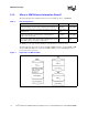
IBMU Functionality 2.1.3 Where Is IPMI-Relevant Information Stored? The following table shows which information is stored in which repository of a BMC/PM. Table 3. Data in Repositories Information Repository Available in Inventory information on board or device: Manufacturer ID, product ID etc. Field Replaceable Unit (FRU) PM and BMC Messages concerning events, such as abnormal voltages, out-of-range temperatures etc.
IBMU Functionality 2.1.4 Basic Communication Principles The system management software communicates with the devices via the BMC. It can communicate with: • Boards/devices with IPMI controller • Boards/devices without IPMI controller (nonintelligent devices) • On-board sensors The following sections describe the basic communication procedure between the system management software and the boards/devices given in the list above. 2.1.4.
IBMU Functionality Figure 2. Required Parts for Communication with IPMI Devices and On-Board Sensors 2.1.5.2 Nonintelligent Devices For the communication between the system management software and nonintelligent devices the following components are necessary: • IPMI driver for operating system • Middleware • System management software Figure 3.
IBMU Functionality 2.1.6 Available Drivers IPMI drivers for the following operating systems are available: • • • • VxWorks* Windows 2000/NT* Solaris* MontaVista Linux* These drivers include an application programming interface (API) to use IPMI commands. Please see Appendix A for an API to use IPMI commands. Additional information regarding implementing this software is available by contacting Force Computers (www.forcecomputers.com). 2.
IBMU Functionality Whereas the Keyboard Controller Style (KCS0) interface and the Intelligent Peripheral Management Buses (IPMB) allow communication between components within one chassis, the KCS0 interface and ICMB connect the devices of one chassis with another chassis. The IPMB and ICMB buses are IBMU powered and will be available even if the CPU board is not powered. Note: On some boards the sensors on the sensor bus are not powered by the IBMU.
IBMU Functionality Note: After installing or removing a board under hot-swap conditions, it is possible that nonintelligent devices will block the IPMB bus. Therefore: • If the device is powered by its own power supply, turn off the device, then turn it on again. • If the device is powered by the system’s power supply, turn off the whole system, then turn on. 2.2.1.1 Devices with IPMI Controller The following describes an easy event handling example for a fan module with IPMI controller.
IBMU Functionality Figure 7. Example for Nonintelligent Devices 2.2.1.3 On-Board Temperature Sensor To read out the actual temperature value from the on-board sensor, the procedure is as follows: 1. The system management software sends the IPMI command “Get Sensor Reading” to the BMC, the BMC reads the value from the on-board sensor and sends it to the system management software. 2. The system management software compares the read value with a threshold value. 3.
IBMU Functionality Figure 9. Intelligent Chassis Management Bus (ICMB) The connection via ICMB is useful for maintenance purposes. If, for example, the CPU board in one chassis hangs, the BMC in the other chassis can read the log file of the affected BMC via ICMB. Another application is the monitoring and controlling of nonintelligent devices.
IBMU Functionality 1. The system management software residing on the CPU board in chassis 2 sends an ICMB message to the BMC2. This ICMB message contains the ICMB header information and the IPMI command “Master Write-Read I2C” with which the fan sensor data is requested. 2. The BMC2 sends the ICMB message to the BMC1 via ICMB. 3. BMC1 extracts the IPMI command “Master Write-Read I2C” from the ICMB message. 4.
Preparing Software for IPMI Usage Preparing Software for IPMI Usage 3.1 3 Action Plan Before being able to use IPMI the following steps are required and will be described in this chapter. 3.2 Notes on Writing Your Own IPMI Driver The Intel® NetStructure™ MPCBL5525 offers IPMI drivers for several operating systems. For information about designing your own IPMI driver, refer to the Intelligent Board Management Unit Reference Guide (PN217328), available by contacting Force Computers.
Preparing Software for IPMI Usage 3.3 Sensor Data Records For each sensor attached to an IPMI controller in a system you need SDRs. SDRs for sensors on Force CPU boards are provided by Force Computers. SDRs for sensors on third-party products must be obtained by the respective manufacturer. 3.3.1 Obtaining SDR Settings To obtain SDR settings (thresholds, whether thresholds can be changed, whether a sensor generates events etc.
Preparing Software for IPMI Usage 3.4.2 Checking CPU Board Signals The IBMU is equipped with several discrete sensors used to check the assertion or deassertion of CPU board signals. After an assertion or deassertion of such a signal, the IPMI controller generates event messages. For further information on event messages, refer to tables 17-5 and 19-1 of the IPMI Specification 1.0. Set as PM, the IPMI controller sends these messages to the BMC in the system.
Preparing Software for IPMI Usage 3.4.2.4 POST Code This sensor allows you to read the board’s POST code with the IPMI command “Get Sensor Reading”. Note: 3.4.3 This sensor does not generate event messages. Monitoring the IBMU The Intel NetStructure MPCBL5525 System Master Board provides the possibility for the system management software to obtain information on a possible IBMU problem source (missing SDRs, memory error, or inaccessible buses).
Supported IPMI Commands and BMC/PM Addresses Supported IPMI Commands and BMC/PM Addresses 4.1 4 Standard IPMI Commands This section provides information on which IPMI commands are supported. All commands are uniquely identified by: • Network function code (NetFn) – Specifies functional category of a command • Command code (CMD) – Byte which specifies the operation The IPMI Specification defines several software channels which allow communication.
Supported IPMI Commands and BMC/PM Addresses 4.2.3 SEL Commands All commands in this category defined as mandatory by the IPMI specification are implemented. In addition, the following optional commands are available. Note: Table 5. SEL commands can only be used in BMC mode. Optional SEL Device Commands Command 4.2.
Supported IPMI Commands and BMC/PM Addresses 4.2.6 Sensor Device Commands All commands in this category defined as mandatory by the IPMI specification are implemented. In addition, the following optional commands are available. Table 7.
Supported IPMI Commands and BMC/PM Addresses Table 8. Implemented Optional ICMB Bridge Commands (Sheet 2 of 2) Command 4.
Supported IPMI Commands and BMC/PM Addresses 4.3.2 FlashFileSystemClear This command is used to delete all the SDR, FRU and SEL repository and to update the FRU data. 4.3.2.1 Request Data Byte - 4.3.2.2 Data Field - Response Data Byte 1 4.3.3 Data Field Completion Code GetGeographicalAddress This command is used to obtain the geographical address of the slot into which the board with the IPMI controller is plugged in and the IPMI controller’s I2C address.
Supported IPMI Commands and BMC/PM Addresses 4.3.4.1 Request Data Byte - 4.3.4.2 Data Field - Response Data Byte 4.3.5 Data Field 1 Completion Code 2 Record count LSB 3 Record count MSB 4 CRC16 LSB 5 CRC16 MSB SetShadowRepositoryEnable This command is used to enable or disable the access to the shadow repository of an IPMI controller in BMC stand-by mode. Note: 4.3.5.1 4.3.5.2 4.4 This command can only be used if IPMI controller is in BMC stand-by mode.
Supported IPMI Commands and BMC/PM Addresses addresses is defined in the PICMG 2.9 Specification and is also shown in the table that follows. The IPMI controller of a board which has the geographical address 4 in a system, for example, can be addressed via I2C address B616. Table 9.
Supported IPMI Commands and BMC/PM Addresses 30 Intel® NetStructure™ MPCHC5525 System Master Processor Board IPMI Reference Driver User’s Guide
Customer Support Customer Support 5.1 5 Customer Support This chapter offers technical and sales assistance information for this product. Information on returning an Intel® NetStructure™ product for service is in the following chapter. 5.2 Technical Support and Return for Service Assistance For all product returns and support issues, please contact your Intel product distributor or Intel Sales Representative for specific information. 5.
Customer Support 32 Intel® NetStructure™ MPCHC5525 System Master Processor Board IPMI Reference Driver User’s Guide