Intel® IXP45X and Intel® IXP46X Product Line of Network Processors Hardware Design Guidelines February 2007 Document No:305261; Revision:004
INFORMATION IN THIS DOCUMENT IS PROVIDED IN CONNECTION WITH INTELR PRODUCTS. EXCEPT AS PROVIDED IN INTEL'S TERMS AND CONDITIONS OF SALE FOR SUCH PRODUCTS, INTEL ASSUMES NO LIABILITY WHATSOEVER, AND INTEL DISCLAIMS ANY EXPRESS OR IMPLIED WARRANTY RELATING TO SALE AND/OR USE OF INTEL PRODUCTS, INCLUDING LIABILITY OR WARRANTIES RELATING TO FITNESS FOR A PARTICULAR PURPOSE, MERCHANTABILITY, OR INFRINGEMENT OF ANY PATENT, COPYRIGHT, OR OTHER INTELLECTUAL PROPERTY RIGHT.
Contents—Intel® IXP45X and Intel® IXP46X Product Line of Network Processors Contents 1.0 Introduction .............................................................................................................. 9 1.1 Content Overview................................................................................................ 9 1.2 Related Documentation ...................................................................................... 10 1.3 Acronyms and Abbreviations .............................
Intel® IXP45X and Intel® IXP46X Product Line of Network Processors—Contents 3.13 3.14 3.15 3.12.1 Signal Interface ......................................................................................48 3.12.2 PCI Interface Block Diagram.....................................................................49 3.12.3 Supporting 5 V PCI Interface ....................................................................50 3.12.4 PCI Option Interface.................................................................
Contents—Intel® IXP45X and Intel® IXP46X Product Line of Network Processors 7.2 7.1.7.1 Clock Group ............................................................................. 88 7.1.7.2 Data, Command, and Control Groups........................................... 89 Simulation Results............................................................................................. 90 7.2.1 Clock Group........................................................................................... 90 7.2.
Intel® IXP45X and Intel® IXP46X Product Line of Network Processors—Contents 44 45 46 47 48 49 50 51 DDR DDR DDR DDR DDR DDR DDR DDR RAS Simulation Results: Two-Bank x16 Devices ....................................................99 Command (MA3) Topology: Two-Bank x16 Devices .............................................. 101 Address Simulation Results: Two-Bank x16 Devices ............................................. 102 Command (RAS) Topology: Two-Bank x16 Devices .....................................
Revision History—Intel® IXP45X and Intel® IXP46X Product Line of Network Processors Revision History Date Revision Description • • February 2007 004 • • • • Section 1.4, Figure 1, Figure 2, Section 3.5: Updated the number of supported SMII ports from six to three. Table 11, Table 12, Table 16: Updated pin type for UTP_OP_ADDR[4:0], UTP_IP_ADDR[4:0], and ETH_MDC. Section 7.0, “DDR-SDRAM” : Updated design information. Removed SS-SMII references since this feature is not supported.
Intel® IXP45X and Intel® IXP46X Product Line of Network Processors—Revision History Intel® IXP45X and Intel® IXP46X Product Line of Network Processors HDD 8 February 2007 Document Number: 305261, Revision: 004
Introduction—Intel® IXP45X and Intel® IXP46X Product Line of Network Processors 1.0 Introduction This design guide provides recommendations for hardware and system designers who are developing with the Intel® IXP45X and Intel® IXP46X Product Line of Network Processors.
Intel® IXP45X and Intel® IXP46X Product Line of Network Processors—Introduction 1.
Introduction—Intel® IXP45X and Intel® IXP46X Product Line of Network Processors 1.3 Acronyms and Abbreviations Table 1 lists the acronyms and abbreviations used in this guide. Table 1.
Intel® IXP45X and Intel® IXP46X Product Line of Network Processors—Introduction • 32-bit PCI interface Master/Target 33/66 MHz • Device Universal Serial Bus (USB) Controller • Host Universal Serial Bus (USB) Controller • DDRI-266 SDRAM (133-MHz Clock, 266-Mbps per data line) — User-enabled ECC, supports up to 1 Gbyte of external memory • 32-bit Expansion Bus Interface — Master/Target interface • Two UART ports • Up to three Ethernet ports (consult device part number for enabled features) MII/ SMII • Up to
Introduction—Intel® IXP45X and Intel® IXP46X Product Line of Network Processors Figure 1. Intel® IXP465 Component Block Diagram HSS 0 HSS 1 UTOPIA 2/MII/SMII NPE A MII/SMII NPE B NPE C MII/SMII North AHB 133.32 MHz x 32 bits AES/DES/SHA/ MD-5 North AHB Arbiter I2 C SSP USB Device Version 1.1 APB 66.
Intel® IXP45X and Intel® IXP46X Product Line of Network Processors—Introduction 1.5 Typical Applications • High-performance DSL modem • High-performance cable modem • Residential gateway • SME router • Integrated access device (IAD) • Set-top box • DSLAM • Access points — 802.
System Architecture—Intel® IXP45X and Intel® IXP46X Product Line of Network Processors 2.0 System Architecture 2.1 System Architecture Description The Intel® IXP45X and Intel® IXP46X Product Line of Network Processors are multifunction processors that integrate the Intel XScale® Processor (ARM* architecture compliant) with highly integrated peripheral controllers and intelligent network processor engines. The processor is a highly integrated design, manufactured with Intel’s 0.
Intel® IXP45X and Intel® IXP46X Product Line of Network Processors—System Architecture Intel® IXP465 Example System Block Diagram Figure 2.
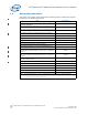
General Hardware Design Considerations—Intel® IXP45X and Intel® IXP46X Product Line of Network Processors 3.0 General Hardware Design Considerations This chapter contains information for implementing and interfacing to major hardware blocks of the Intel® IXP45X and Intel® IXP46X Product Line of Network Processors. Such blocks include DDR SDRAM, Flash, SRAM, Ethernet PHYs, UART and most other peripherals interfaces. Signal definition tables list resistor recommendations for pullups and pull-downs.
Intel® IXP45X and Intel® IXP46X Product Line of Network Processors—General Hardware Design Considerations Table 3. Soft Fusible Features Name PCI The complete bus must be enabled or disable. HSS0/1 Can only be disable as a pair. UTOPIA If enabling UTOPIA, MACs on NPE A are disabled. If enabling MACs on NPE A, UTOPIA are disabled. ETHERNET Can Enable either MII MACs or SMII MACs, but not both at the same time. Enable of MACs can be separately done per each NPE.
General Hardware Design Considerations—Intel® IXP45X and Intel® IXP46X Product Line of Network Processors Table 4. DDR SDRAM Interface Pin Description (Sheet 2 of 2) Input Outpu t Device-Pin Connection VTT Terminatio n Description O The WE signal must be connected to each device in a daisy chain manner Yes Write Strobe — Defines whether or not the current operation by the DDR SDRAM is to be a read or a write. DDRI_DM[4:0] O Connect to each DM device pin.
Intel® IXP45X and Intel® IXP46X Product Line of Network Processors—General Hardware Design Considerations 3.2.2 DDR SDRAM Memory Interface The IXP45X/IXP46X network processors support compatible DDR-266 SDRAM, 8- and 16-bit wide devices, with a total bus width of 32 bits. Only 32-bit-wide accesses are supported. The maximum supported memory is 1 Gbyte, configured by enabling both physical banks of DDR-266 SDRAM devices.
General Hardware Design Considerations—Intel® IXP45X and Intel® IXP46X Product Line of Network Processors 3.3.1 Signal Interface Table 5. Expansion Bus Signal Recommendations Name Input Output Pull Up Down Recommendations EX_CLK I No Use series termination resistor, 10Ω to 33Ω at the source. EX_ALE TRI O No Use series termination resistor, 10Ω to 33Ω at the source. Yes Use 4.7-KΩ resistors for pull-downs; required for boot strapping for initial configuration of Configuration Register 0.
Intel® IXP45X and Intel® IXP46X Product Line of Network Processors—General Hardware Design Considerations For a complete bit description of Configuration Register 0, see the Intel® IXP45X and Intel® IXP46X Product Line of Network Processors Developer’s Manual. Table 6.
General Hardware Design Considerations—Intel® IXP45X and Intel® IXP46X Product Line of Network Processors Table 6. Boot/Reset Strapping Configuration (Sheet 2 of 2) Name Function EX_ADDR[2] PCI_ARB EX_ADDR[1] PCI_HOST EX_ADDR[0] 3.3.
Intel® IXP45X and Intel® IXP46X Product Line of Network Processors—General Hardware Design Considerations For example, as in this case when booting of a 16-bit flash device, bit 0 and 7 of Configuration Register 0 must be set as follows: • Bit 0 = 0. This can be done by placing an external 4.7-KΩ pull-down resistor to pin EX_ADDR[0]. • Bit 7 = 0. This can be done by placing an external 4.7-KΩ pull-down resistor to pin EX_ADDR[7].
General Hardware Design Considerations—Intel® IXP45X and Intel® IXP46X Product Line of Network Processors Figure 3.
Intel® IXP45X and Intel® IXP46X Product Line of Network Processors—General Hardware Design Considerations Figure 4.
General Hardware Design Considerations—Intel® IXP45X and Intel® IXP46X Product Line of Network Processors 3.3.6 Flash Interface Figure 5 illustrates how a boot ROM is connected to the expansion bus. The flash (ROM) used in the block diagram is the Intel StrataFlash® memory device TE28F256J3D — 32-Mbyte, 16-bit, flash in the 56-TSOP package. The Intel StrataFlash memory TE28F256J3D is part of the 0.13-micron, 3.3-V Intel StrataFlash memory. The E28F256J3D supports common flash interface (CFI).
Intel® IXP45X and Intel® IXP46X Product Line of Network Processors—General Hardware Design Considerations 3.3.7 SRAM Interface A typical connection between an 8-bit SRAM memory device and the IXP45X/IXP46X network processors expansion bus is shown in Figure 6 on page 28. When attempting to communicate to this device, the Timing and Control Register for Chip Select must be configured for proper access.
General Hardware Design Considerations—Intel® IXP45X and Intel® IXP46X Product Line of Network Processors Note: The UART module does not support full modem functionality. However, this can be implemented, by using GPIO ports to generate DTR, DSR, RI, and DCD and making some changes to the driver. 3.4.1 Signal Interface Table 7. UART Signal Recommendations Name Input Output Pull Up Down RXDATA0 I Yes Serial data input Port 0.
Intel® IXP45X and Intel® IXP46X Product Line of Network Processors—General Hardware Design Considerations Figure 7. UART Interface Example UART Interface DB9 Connector CTS1_N OUT4 RTS1_N IN3 RXDATA1 TXDATA1 6 IN1 2 RX 3 TX 4 DTR 3 8 NC RS-232 Transceiver 2 1 DCD 7 OUT1 OUT3 OUT2 IN2 IN4 ® Intel IXP46X ® Intel Line IXP46X Product of Product Line of Network Processors Network Processors 1 9 5 GND 4 6 DSR 5 8 CTS 7 RTS 9 RI B4099 -003 3.
General Hardware Design Considerations—Intel® IXP45X and Intel® IXP46X Product Line of Network Processors 3.5.1 Signal Interface MII Table 8. MII NPE A Signal Recommendations Input/ Output Pull Up Down ETHA_TXCLK I Yes Transmit Clock. When this interface/signal is enabled and is not being used in a system design, the interface/signal should be pulled high with a 10-KΩ resistor. ETHA_TXDATA[3:0] O No Transmit Data. ETHA_TXEN O No Transmit Enable. ETHA_RXCLK I Yes Receive Clock.
Intel® IXP45X and Intel® IXP46X Product Line of Network Processors—General Hardware Design Considerations Table 9. MII NPE B Signal Recommendations (Sheet 2 of 2) Input/ Output Pull Up/ Down ETHB_COL I Yes Collision Detect. If operating in a full duplex mode and there is no requirement to use the Collision Detect signal, then the pin must be pulled low with a 10-KΩ resistor. ETHB_CRS I Yes Carrier Sense.
General Hardware Design Considerations—Intel® IXP45X and Intel® IXP46X Product Line of Network Processors Table 11. Name MAC Management Signal Recommendations NPE A,B,C Input/ Output Pull Up/ Down Recommendations ETH_mdio I/O Yes NPE A,B,C Management data output. An external pull-up resistor of 1.5 KΩ is required on ETH_MDIO to properly quantify the external PHYs used in the system. For specific implementation, see the IEEE 802.3 specification.
Intel® IXP45X and Intel® IXP46X Product Line of Network Processors—General Hardware Design Considerations 3.5.3 Signal Interface, SMII Serial Media Independent Interface (SMII) is a hardware feature to convey complete MII interface between a MAC and 10/100 PHY interface with two data pins per port and one synchronizing signal for multi PHYs. Table 12. SMII Signal Recommendations: NPE A, B, C Name SMII_TXDATA[4] Input/ Output Pull Up/ Down O No NPE A Transmit Data Port 4.
General Hardware Design Considerations—Intel® IXP45X and Intel® IXP46X Product Line of Network Processors 3.5.4 Device Connection, SMII Figure 9. SMII Interface Example ® Intel IXP46X Product Line Network Processor 10/100 PHY SMII_TXSYNC TXSYNC SMII_TXDATA TXDATA SMII_RXDATA RXDATA Magnetics VCC (3.3 V) RJ45 1.5 KΩ ETH_MDIO ETH_MDC MDIO MDC 125 MHz SMII_CLK REF CLK SMII Interface B 4103- 002 3.
Intel® IXP45X and Intel® IXP46X Product Line of Network Processors—General Hardware Design Considerations 3.6.1 Signal Interface Table 13. GPIO Signal Recommendations Name Input/ Output Pull Up/ Down Recommendations GPIO[12:0] I/O Yes General Purpose Input/Output. If used as an input interrupt, should be pull-up or pull-down, depending on the level of activation. For example: Active high, use a 10-KΩ pull-down resistor. Active low, use a 10-KΩ pull-up resistor.
General Hardware Design Considerations—Intel® IXP45X and Intel® IXP46X Product Line of Network Processors 3.7 I2C Interface The IXP45X/IXP46X network processors support I2C interface and protocol. The hardware-embedded block supports transfer rates in Standard-mode at up to 100 Kbps or Fast-mode at up to 400 Kbps, 7-bit addressing, and Master or Slave mode. Note: The I2C block does not support 10-bit addressing mode.
Intel® IXP45X and Intel® IXP46X Product Line of Network Processors—General Hardware Design Considerations Figure 10. I2C EEPROM Interface Example 1 A0 2 A1 WP SCL 3 A2 SDA I2C EEPROM GND 4.7 KΩ 4.7 KΩ 8 VCC 4.7 KΩ 3.3 V 0.1 µF Intel® IXP46X Product Line Network Processor 7 6 I2C_SCL 5 I2C_SDA 4 I2C_SCL I2C_SDA I2C Interface I 2C Interface B 4104-002 3.
General Hardware Design Considerations—Intel® IXP45X and Intel® IXP46X Product Line of Network Processors 3.8.1 Signal Interface Table 15. USB Host/Device Signal Recommendations Name USB_DPOS Input/ Output Pull Up/ Down I/O Yes Positive signal of the differential USB receiver/driver for the USB device interface. Use an 18Ω series termination resistor at the source.
Intel® IXP45X and Intel® IXP46X Product Line of Network Processors—General Hardware Design Considerations To maintain signal integrity and minimize end-users termination mismatch, the IXP45X/IXP46X network processors require external series termination resistors. The value of terminating resistors is based on the operational speed and length of the transmission line. It is recommended to start with a 18-Ω resistor and adjust the value if required.
General Hardware Design Considerations—Intel® IXP45X and Intel® IXP46X Product Line of Network Processors Figure 12. USB Device Interface Example Device Host Intel® IXP46X Product Line Network Processor V_BUS USB_3V3 V_BUS 1.5 KΩ Look at Note 1&2 USB_DPOS (D+) 18 Ω FERRITE D + 22 pF 22 pF D- USB Port USB_DNEG (D-) 15 KΩ 18 Ω HOST 15 KΩ FERRITE 22 pF 22 pF B4106-003 3.
Intel® IXP45X and Intel® IXP46X Product Line of Network Processors—General Hardware Design Considerations 3.9.1 Signal Interface Table 16. UTOPIA Signal Recommendations Input/ Output Pull Up/ Down UTP_OP_CLK I Yes UTOPIA Transmit clock input. Also known as UTP_TX_CLK. When this interface/signal is enabled and is not being used in a system design, the interface/signal should be pulled high with a 10-KΩ resistor. UTP_OP_FCO O Yes UTOPIA flow control output signal.
General Hardware Design Considerations—Intel® IXP45X and Intel® IXP46X Product Line of Network Processors Figure 13.
Intel® IXP45X and Intel® IXP46X Product Line of Network Processors—General Hardware Design Considerations 3.10.1 Signal Interface Table 17. High-Speed, Serial Interface 0 Input Output Pull Up Down HSS_TXFRAME0 I/O Yes Transmit frame. When this interface/signal is enabled and is not being used in a system design, the interface/signal should be pulled high with a 10-KΩ resistor. HSS_TXDATA0 OD Yes Transmit data out. Open Drain Output.
General Hardware Design Considerations—Intel® IXP45X and Intel® IXP46X Product Line of Network Processors Table 18. High-Speed, Serial Interface 1 Input Output Pull Up Down HSS_TXFRAME1 I/O Yes Transmit frame. When this interface/signal is enabled and is not being used in a system design, the interface/signal should be pulled high with a 10-KΩ resistor. HSS_TXDATA1 OD Yes Transmit data out. Open Drain output.
Intel® IXP45X and Intel® IXP46X Product Line of Network Processors—General Hardware Design Considerations 3.10.2 Device Connection Figure 14 shows a typical interface between the IXP45X/IXP46X product line and a SLIC CODEC, via the SSP and HSS ports, and a couple of GPIO signals. Figure 14. HSS Interface Example Vccp (3.3 V) Intel® IXP46X Product Line of Network Processors External Oscillator 10 KΩ GPIO_0 GPIO_1 Clock derived internally from 3.
General Hardware Design Considerations—Intel® IXP45X and Intel® IXP46X Product Line of Network Processors 3.11.1 Signal Interface Table 19. Synchronous Serial Peripheral Port Interface Name Input/ Output Pull Up/ Down Recommendations SSP_SCLK O No Serial bit clock. SSP_SFRM O No Serial frame indicator. SSP_TXD O No Transmit data (serial data out). SSP_RXD I Yes Receive data (serial data in). Should be pulled high through a 10-KΩ resistor when not being utilized in the system.
Intel® IXP45X and Intel® IXP46X Product Line of Network Processors—General Hardware Design Considerations 3.12 PCI Interface The PCI Controller of the IXP45X/IXP46X network processors is an industry-standard, 32-bit interface, high-performance bus that operates at either 33 or 66 MHz (PCI Local Bus Specification, Rev. 2.2). The PCI Controller supports operation as a PCI host and implements a PCI arbiter for a system containing up to four external PCI devices.
General Hardware Design Considerations—Intel® IXP45X and Intel® IXP46X Product Line of Network Processors Table 20. Name PCI Controller (Sheet 2 of 2) Input/ Pull Up/ Outpu Down t Recommendations PCI_IDSEL I Yes Initialization Device Select. When this interface/signal is enabled and is not being used in a system design, the interface/ signal should be pulled high with a 10-KΩ resistor. PCI_REQ_N[3:1] I Yes Arbitration Request.
Intel® IXP45X and Intel® IXP46X Product Line of Network Processors—General Hardware Design Considerations Figure 16. PCI Interface cPCI J2 Compact PCI Bus PCI Interface PCI Bus Transparent PCI Bridge cPCI J1 Intel ® IXP46X Product Line Network Processor PCI Slots B 4110- 001 3.12.3 Supporting 5 V PCI Interface It is possible to support 5 V PCI devices with the help of voltage logic translators. One option can be implemented with voltage level translator.
General Hardware Design Considerations—Intel® IXP45X and Intel® IXP46X Product Line of Network Processors Figure 17. PCI 3.3 V to 5 V Logic Translation Interface Intel ® IXP46X Product Line Network Processor 3.3V LOGIC 3.3V Logic PCI Device_ 1 3.3V LOGIC 3.3V Logic PCI Device_2 3.3V LOGIC 32-Bit BUS 3.3V Logic PCI Device_3 5.0V 1K 74CBT3384A OE VCC PCI Interface 4.3V 10-BIT GND 5.0V LOGIC 3.3V LOGIC VCC 10-BIT 1K OE 5.0V Logic PCI Device_4 2.87K GND 74CBT3384A B5197 -01 3.12.
Intel® IXP45X and Intel® IXP46X Product Line of Network Processors—General Hardware Design Considerations Table 21. Name PCI Host/Option Interface Pin Description (Sheet 2 of 3) Host Input Outpu t Device-Pin Connection Option Input Outpu t Description PCI_TRDY_N I/O Connect signal to same pin between the two devices. Connect a 10-KΩ pull-up resistor. I/O PCI Target Ready PCI_IRDY_N I/O Connect signal to same pin between the two devices. Connect a 10-KΩ pull-up resistor.
General Hardware Design Considerations—Intel® IXP45X and Intel® IXP46X Product Line of Network Processors Table 21. Name PCI_INTA_N PCI_CLKIN 3.12.5 PCI Host/Option Interface Pin Description (Sheet 3 of 3) Host Input Outpu t Device-Pin Connection O/D Connect PCI_INTA_N output from the Option to one of the GPIO input signals of the Host. The GPIO signal at the Host must be configure as an input interrupt level sensitive. I Clock must be connected to both devices. Trace lengths must be matched.
Intel® IXP45X and Intel® IXP46X Product Line of Network Processors—General Hardware Design Considerations 3.13.1 Signal Interface Table 22. Synchronous Serial Peripheral Port Interface Name Input/ Output Pull Up/ Down JTG_TMS I Yes Test mode select. When the JTAG interface is not being used, the signal must be pulled high using a 10-kΩ resistor. JTG_TDI I Yes Test Input data. When the JTAG interface is not being used, the signal must be pulled high using a 10-kΩ resistor.
General Hardware Design Considerations—Intel® IXP45X and Intel® IXP46X Product Line of Network Processors 3.14.3 Device Connection Figure 18. Clock Oscillator Interface Example 3.3 V OSC_IN OUT VDD 33 Ω ON 10 KΩ 0.01 µF 33.33 MHz OSC_OUT Intel ® IXP46X Product Line of Network Processors B4111 -001 3.15 Power To enable low power system design, the IXP45X/IXP46X network processors have separate power supply domains for the processor core, DDR SDRAM memory, and input/output peripherals.
Intel® IXP45X and Intel® IXP46X Product Line of Network Processors—General Hardware Design Considerations Table 24. Name Power Interface (Sheet 2 of 2) Nominal Voltage Description VCCPLL1 1.3 V Supply voltage for internal logic of analog phase lock-loop circuitry. Requires special power filtering circuitry. If operating at 667 MHz, this voltage must be increased to 1.5 V. See the Intel® IXP45X and Intel® IXP46X Product Line of Network Processors Datasheet. VCCPLL2 1.
General Hardware Design Considerations—Intel® IXP45X and Intel® IXP46X Product Line of Network Processors For a complete description of their functionality, see the Intel® IXP45X and Intel® IXP46X Product Line of Network Processors Datasheet and its section titled “Reset Timings.” PWRON_RESET_N is used as a Power Good and RESET_IN_N is used for resetting internal registers.
Intel® IXP45X and Intel® IXP46X Product Line of Network Processors—General Hardware Design Considerations Intel® IXP45X and Intel® IXP46X Product Line of Network Processors HDD 58 February 2007 Document Number: 305261; Revision: 004
General PCB Guide—Intel® IXP45X and Intel® IXP46X Product Line of Network Processors 4.0 General PCB Guide 4.1 PCB Overview Beginning with components selection, this chapter presents general PCB guidelines. In cases where it is too difficult to adhere to a guideline, engineering judgment must be used. The methods are listed as simple DOs and DON’Ts. This chapter does not discuss the functional aspects of any bus, or layout guides for any interfaced devices. 4.
Intel® IXP45X and Intel® IXP46X Product Line of Network Processors—Category Figure 19. Component Placement on a PCB C O N N E C T O R Medium Frequency High Frequency Components Analog Circuit Low Frequency PCB B2264-01 • Place noisy parts (clock, processor, video, etc.) at least 1.5 – 3 inches away from the edge of the printed circuit board.
General PCB Guide—Intel® IXP45X and Intel® IXP46X Product Line of Network Processors • Poor routing density • Uncontrolled signal trace impedance • Lack of power/ground planes, resulting in unacceptable cross-talk • Relatively high-impedance power distribution circuitry, resulting in noise on the power and ground rails • High-speed circuits require multi-layer printed circuit boards: — Advantages: • Controlled-impedance traces • Low-impedance power distribution — Disadvantages: • Higher cost • More weigh
Intel® IXP45X and Intel® IXP46X Product Line of Network Processors—Category Figure 20. 8-Layer Stackup 4.5 mil Component (Top) Side Legend 5 mil Data L1 Data GND L2 Data SIGNAL 7 mil 17.8 mil L3 L4 7 mil 62 mil POWER 5 mil Data L5 Data 4.5 mil L6 Data L7 Solder (Bottom) Side L8 B2244-02 Figure 21. 6-Layer Stackup Legend SIGNAL 4.5 mil 7 mil Component (Top) Side L1 GND ~40 mil L2 7 mil 62 mil L3 4.
General Layout and Routing Guide—Intel® IXP45X and Intel® IXP46X Product Line of Network Processors 5.0 General Layout and Routing Guide 5.1 Overview This chapter provides routing and layout guides for hardware and systems based on the Intel® IXP45X and Intel® IXP46X Product Line of Network Processors. The high-speed clocking required when designing with the processors requires special attention to signal integrity.
Intel® IXP45X and Intel® IXP46X Product Line of Network Processors—Category • Do not place high-frequency oscillators and switching network devices close to sensitive analog circuits. • Arrange the board so that return currents for high-speed traces never must jump between planes. Restrict traces to remain on either side of whichever ground plane they start out nearest. This allows the use of naturally grouped horizontal and vertical routing layers.
General Layout and Routing Guide—Intel® IXP45X and Intel® IXP46X Product Line of Network Processors Figure 23. Good Design Practice for VIA Hole Placement 25 mils min 25 mils min 25 mils min B2266-01 Figure 23 and Figure 24 show good and poor design practices for via placement on surface-mount boards. Figure 25 shows minimum pad-to-pad clearance for surface-mount passive components and PGA or BGA components. Figure 24.
Intel® IXP45X and Intel® IXP46X Product Line of Network Processors—Category Figure 25. Pad-to-Pad Clearance of Passive Components to a PGA or BGA PGA or BGA Package 60 mils min 60 mils min 60 mils min B2268-01 5.2.2 Clock Signal Considerations • Provide good return current paths for clock traces. • Keep clock traces away from the edge of the board and any other high-speed devices or traces. • Keep clock traces away from analog signals, including voltage reference signals.
General Layout and Routing Guide—Intel® IXP45X and Intel® IXP46X Product Line of Network Processors — Calculate capacitive loading of all components and properly compensate with a series or parallel terminations. • Measure and match trace lengths for devices that interface with each other and have their clock derived from the same source. If traces must be long, treat them as transmission lines. Terminate clock traces to match trace impedance.
Intel® IXP45X and Intel® IXP46X Product Line of Network Processors—Category • Wherever possible, use a perfect symmetry within a differential pair. • Minimize the number vias. • Avoid routing other signals close by or in parallel to the differential pair, maintaining no less than 50 mil to any other signal. • Maintain control impedance for each differential pair to 90 Ω +/- 15 Ω. • Use high value ferrite beads (100 MHz/60 Ω – 100 MHz/240 Ω). 5.2.
General Layout and Routing Guide—Intel® IXP45X and Intel® IXP46X Product Line of Network Processors 5.2.8 Trace Impedance All signal layers require controlled impedance of 50 Ω ±10 % microstrip or stripline (unless otherwise specified) where appropriate. Selecting the appropriate board stackup to minimize impedance variations is very important. When calculating flight times, it is important to consider the minimum and maximum trace impedance based on the switching neighboring traces. 5.2.
Intel® IXP45X and Intel® IXP46X Product Line of Network Processors—Category Intel® IXP45X and Intel® IXP46X Product Line of Network Processors HDD 70 February 2007 Document Number: 305261; Revision: 004
PCI Interface Design Considerations—Intel® IXP45X and Intel® IXP46X Product Line of Network Processors 6.0 PCI Interface Design Considerations The Intel® IXP45X and Intel® IXP46X Product Line of Network Processors has a single, 32-bit PCI device module that runs at 33/66 MHz. This chapter describes some basic guidelines to help design hardware that interfaces with PCI devices. The PCI module is compatible with the PCI Local Bus Specification, Rev. 2.2.
Intel® IXP45X and Intel® IXP46X Product Line of Network Processors—PCI Interface Design Considerations Figure 26. PCI Address/Data Topology Intel® IXP46X Product Line Network Processor PCI Slot A PCI Slot B PCI Slot B PCI Slot B B5196 -01 Table 25. 6.
PCI Interface Design Considerations—Intel® IXP45X and Intel® IXP46X Product Line of Network Processors Figure 27. PCI Clock Topology PCI Devices A B Rs 33/66 MHz Clock Driver A A B Rs B Rs Intel® IXP46X Product Line Network Processor B4114 -02 Table 26. PCI Clock Routing Guidelines Parameter 6.3.
Intel® IXP45X and Intel® IXP46X Product Line of Network Processors—PCI Interface Design Considerations The limitations of the maximum trace length can be calculated with the equations shown in Section 6.2. Solve for TPROP and use it to calculate the maximum trace length. This is a straight-forward calculation, but very critical to meet timing. It is recommended to keep the trace lengths as short as possible and not to exceed TPROP.
DDR-SDRAM—Intel® IXP45X and Intel® IXP46X Product Line of Network Processors 7.0 DDR-SDRAM 7.1 Introduction This document is intended to be used as a guide for routing DDR, based on the Intel® IXDP465 Development Platform. It contains routing guidelines and simulation results for using x16 Thin Small Outline Package (TSOP) memory devices soldered onto the processor module.
Intel® IXP45X and Intel® IXP46X Product Line of Network Processors—Category Processor-DDR Interface DDRI_DQ[31:0] DATA[31:0] DDRI_MA[13:0] ADDRESS[13:0] A[13:0] CLOCK[2:0], CLOCK#[2:0] CK[2:0] CK#[2:0] CLOCK ENABLE[1:0] CKE[1:0] DDRI_CS_N[1:0] CHIP SELECT#[1:0] CS#[1:0] DDRI_BA[1:0] BANK SELECT[1:0] BA[1:0] DDRI_CB[7:0] ECC DATA[7:0] DQ[7:0] DDRI_DM[4:0] DATA MASK[4:0] DM[4:0] DDRI_DQS[4:0] DATA STROBE[4:0] DQS[4:0] DDRI_WE_N DDRI_RAS_N DDRI_CAS_N WRITE#, RAS#, CAS# DDRI_CK[2:0]
DDR-SDRAM—Intel® IXP45X and Intel® IXP46X Product Line of Network Processors Besides assigning clock signals (DDRI_CK and DDRI_CK_N) to the memory devices, there are two more requirements, one implemented in hardware (termination) and the other implemented in software (configuration), these requirements are explained as follow: • It is recommended to properly terminate the clock output signals by the Thevenin terminations scheme as shown in Figure 37.
Intel® IXP45X and Intel® IXP46X Product Line of Network Processors—Category Table 28.
DDR-SDRAM—Intel® IXP45X and Intel® IXP46X Product Line of Network Processors Figure 29.
Intel® IXP45X and Intel® IXP46X Product Line of Network Processors—Category 7.1.1 Selecting VTT Power Supply Selecting the minimum power requirement for VTT supply is a simple calculation that varies depending on the resistive value of RVTT terminating resistors. Since all RVTT has the same value, the power calculation becomes a simple, current times voltage times the number of terminating resistors used.
DDR-SDRAM—Intel® IXP45X and Intel® IXP46X Product Line of Network Processors 7.1.2 Signal-Timing Analysis Figure 31. DDR Command and Control Setup and Hold T1 T2 T3 T4 T5 T6 DDR_M_CLK Control/Command Valid B3988-001 Table 29. DDR Command and Control Setup and Hold Values Symbol Parameter Min Max Units Notes T1 Output of IXP45X/IXP46X network processors valid for Command and Control signals prior to the transition of DDR_M_CLK 1.
Intel® IXP45X and Intel® IXP46X Product Line of Network Processors—Category Figure 32. DDR Data to DQS Read Timing Parameters T1 T4 T7 T2 T3 DQS Data D0 D1 T8 T6 T5 B3989-001 Table 30. DDR Data to DQS Read Timing Parameters Symbol Parameter T1 Min Max Units Notes IXP45X/IXP46X network processors delay for data group valid after any edge of DQS 0.75 ns 1 T2 IXP45X/IXP46X network processors guaranteed time before data group begins to transition invalid prior to DQS 1.
DDR-SDRAM—Intel® IXP45X and Intel® IXP46X Product Line of Network Processors Figure 33. DDR-Data-to-DQS-Write Timing Parameters T1 T2 T3 T4 T5 DQS T6 Data Data Valid B3990-001 Table 31. DDR Data to DQS Write Timing Parameters Symbol Parameter Min T1 IXP45X/IXP46X network processors output valid for data group signals prior to the transition of DQS T2 Max Units Notes 1.0 ns 1 IXP45X/IXP46X network processors output hold time for data group signals after the transition of DQS 1.
Intel® IXP45X and Intel® IXP46X Product Line of Network Processors—Category Table 32. DDR-Clock-to-DQS-Write Timing Parameters Symbol Parameter Min Max Units Notes T1 IXP45X/IXP46X network processors output valid for DDRI_DQS prior to the transition of DDR_M_CLK 1.4 ns 1 T2 IXP45X/IXP46X network processors output hold time for DDRI_DQS after the transition of DDR_M_CLK 1.0 ns 1 T3 Required write command to DQS latching transition at DDR memory device (early transition) 1.
DDR-SDRAM—Intel® IXP45X and Intel® IXP46X Product Line of Network Processors Figure 35. Printed Circuit Board Layer Stackup 7.1.4 Printed Circuit Board Controlled Impedance Controlled impedance for each layer of the IXDP465 platform x16 Processor Module is necessary to provide proper matching from driver to receiver(s) for improved signal integrity and higher reliability in the signal analysis results obtained through simulation.
Intel® IXP45X and Intel® IXP46X Product Line of Network Processors—Category Figure 36.
DDR-SDRAM—Intel® IXP45X and Intel® IXP46X Product Line of Network Processors 7.1.5 Timing Relationships The routing guidelines presented in the following subsections define the recommended routing topologies, trace width, spacing geometries, and typical routed lengths for each signal group. These parameters are recommended to achieve optimal signal integrity and timing. All signal groups are length matched to the DDR clocks.
Intel® IXP45X and Intel® IXP46X Product Line of Network Processors—Category In addition to any trace length differentials which must be considered between signal groups, differences in the package length between signals should be considered when determining the total propagation delay of the signals. When using the IBIS model for signal analysis, package characteristics are included in the simulation results. 7.1.
DDR-SDRAM—Intel® IXP45X and Intel® IXP46X Product Line of Network Processors Table 34. Clock Signal Group Routing Guidelines Parameter Definition Signal Group Members DDRI_CK[2:0] and DDRI_CK_N[2:0] Topology Differential Pair Point to Point (1 Driver, 2 Receivers) Single Ended Trace Impedance (Zo) 60 Differential Mode Impedance (Zdiff ) 120 Ωs Ωs Nominal Trace Width1 Internal (Strip Line) 3.5 mils, External (Micro Strip) 5 mils Nominal Pair Spacing (edge to edge) 2 Internal (Strip Line) 10.
Intel® IXP45X and Intel® IXP46X Product Line of Network Processors—Category 7.2 Simulation Results This section contains the simulation results for each of the DDR signal groups. Each of the signal groups may have different overall topologies based on the number of banks and ECC usage. Each signal group simulated below uses a two-bank, 32-bit data bus with ECC based on 16-bit DDR devices. 7.2.1 Clock Group The clock signal group includes the differential clock pairs DDRI_CK[2:0] and DDRI_CK_N[2:0].
DDR-SDRAM—Intel® IXP45X and Intel® IXP46X Product Line of Network Processors Figure 37.
Intel® IXP45X and Intel® IXP46X Product Line of Network Processors—Category Figure 38. DDR Clock Simulation Results: Two-Bank x16 Devices The differential-clock-circuit simulation in Figure 38 shows that the voltage waveform meets the DDR device input voltage requirements. The crossing point for the clock input must occur between Vix(min) =1.05 V and Vix(max) =1.45 V and have a minimum peak to peak swing of 700 mV. The receiver input waveform must also not exceed a maximum voltage of Vin(max) =2.
DDR-SDRAM—Intel® IXP45X and Intel® IXP46X Product Line of Network Processors Table 37.
Intel® IXP45X and Intel® IXP46X Product Line of Network Processors—Category Figure 39.
DDR-SDRAM—Intel® IXP45X and Intel® IXP46X Product Line of Network Processors Figure 40. DDR Data Write Simulation Results: Two-Bank x16 Devices The data-circuit simulation results in Figure 40 show that the voltage waveform meets the DDR device input voltage requirements. Vil(max) of Vref – 0.310 or 940 mV and Vih(min) of Vref + 0.310 or 1.56 V are easily achieved at the receiver (DDR_DEVICE1). The receiver waveform must also not exceed a maximum voltage of Vin(max) = 2.
Intel® IXP45X and Intel® IXP46X Product Line of Network Processors—Category Figure 41. DDR Data Read Simulation Results: Two-Bank x16 Devices (Reduced Drive Strength) The simulation results in Figure 41 are for the data circuit with a DDR device using reduced drive strength and shows that the voltage waveform meets the DDR device input voltage requirements. Vil(max) of Vref – 0.150 or 1.10 V and Vih(min) of Vref + 0.150 or 1.40 V are easily achieved at the receiver (IXP45X/IXP46X network processors).
DDR-SDRAM—Intel® IXP45X and Intel® IXP46X Product Line of Network Processors Figure 42. DDR Data Read Simulation Results: Two-Bank x16 Devices (Full Drive Strength) The simulation results in Figure 42 are for the data circuit with a DDR device using full drive strength and show that the voltage waveform meets the DDR device input voltage requirements. Vil(max) of Vref – 0.150 or 1.10 V and Vih(min) of Vref + 0.150 or 1.40 V are easily achieved at the receiver (IXP45X/IXP46X network processors).
Intel® IXP45X and Intel® IXP46X Product Line of Network Processors—Category 7.2.3 Control Group The control signal group includes the signals DDRI_CS[1:0] and DDRI_CKE[1:0]. The following simulations were constructed for the 2 bank x16 device configuration where each signal would have three receivers. Table 38 identifies the transmission line lengths for the chip select (CS0) topology shown in Figure 43 on page 98.
DDR-SDRAM—Intel® IXP45X and Intel® IXP46X Product Line of Network Processors Figure 44. DDR RAS Simulation Results: Two-Bank x16 Devices The simulation results in Figure 44 are for the control circuit and show that the voltage waveform meets the DDR device input voltage requirements. Vil(max) of Vref – 0.310 or 940 mV and Vih(min) of Vref + 0.310 or 1.56 V are easily achieved at the receiver (DDR_DEVICE1). The receiver waveform must also not exceed a maximum voltage of Vin(max) = 2.
Intel® IXP45X and Intel® IXP46X Product Line of Network Processors—Category 7.2.4 Command Group The command signal group includes the signals DDRI_MA[13:0], DDRI_BA[1:0], DDRI_RAS, DDRI_CAS and DDRI_WE. The following simulations were constructed for the 2 bank x16 device configuration where each signal would have six receivers. Table 39 identifies the transmission line lengths for the address (DDRI_MA3) topology shown in Figure 45 and Figure 47.
DDR-SDRAM—Intel® IXP45X and Intel® IXP46X Product Line of Network Processors Figure 45.
Intel® IXP45X and Intel® IXP46X Product Line of Network Processors—Category Figure 46. DDR Address Simulation Results: Two-Bank x16 Devices The simulation results in Figure 46 are for the address circuit and show that the voltage waveform meets the DDR device input voltage requirements. Vil(max) of Vref – 0.310 or 940 mV and Vih(min) of Vref + 0.310 or 1.56 V are easily achieved at the receiver (DDR_DEVICE1). The receiver waveform must also not exceed a maximum voltage of Vin(max) = 2.
DDR-SDRAM—Intel® IXP45X and Intel® IXP46X Product Line of Network Processors Figure 47.
Intel® IXP45X and Intel® IXP46X Product Line of Network Processors—Category Figure 48. DDR RAS Simulation Results: Two-Bank x16 Devices The simulation results in Figure 48 are for the RAS circuit, the voltage waveform meets the DDR device input voltage requirements. Vil(max) of Vref – 0.310 or 940 mV and Vih(min) of Vref + 0.310 or 1.56 V are easily achieved at the receiver (DDR_DEVICE1). The receiver waveform must also not exceed a maximum voltage of Vin(max) = 2.
DDR-SDRAM—Intel® IXP45X and Intel® IXP46X Product Line of Network Processors 7.2.5 RCVENIN and RCVENOUT The Receive Enable In (RCVENIN) and Receive Enable Out (RCVENOUT) should be connected and routed to match the length of the clock signal plus the average data signal trace. This length matching is important to insure the signal propagation delay of RCVENIN/RCVENOUT is the same as that for the clock plus average DQ length.
Intel® IXP45X and Intel® IXP46X Product Line of Network Processors—Category Figure 50. DDR RCVENIN/RCVENOUT Simulation Results (Rseries = 0 Ω) The simulation results in Figure 50 are for the RCVENIN/RCVENOUT circuit with a 0-Ω series resistor, the voltage waveform meets the DDR device input voltage requirements. Vil(max) of Vref – 0.150 or 1.10 V and Vih(min) of Vref + 0.150 or 1.40 V are easily achieved at the receiver (RCVENIN).
DDR-SDRAM—Intel® IXP45X and Intel® IXP46X Product Line of Network Processors Figure 51. DDR RCVENIN/RCVENOUT Simulation Results (Rseries = 60 Ω) The simulation results in Figure 51 are for the RCVENIN/RCVENOUT circuit, the voltage waveform meets the DDR device input voltage requirements. Vil(max) of Vref – 0.150 or 1.10 V and Vih(min) of Vref + 0.150 or 1.40 V are easily achieved at the receiver (RCVENIN). The receiver waveform must also not exceed a maximum voltage of Vin(max) = 2.
Intel® IXP45X and Intel® IXP46X Product Line of Network Processors—Category Intel® IXP45X and Intel® IXP46X Product Line of Network Processors HDD 108 February 2007 Document Number: 305261, Revision: 004