Intel® IXP43X Product Line of Network Processors Hardware Design Guidelines April 2007 Document Number: 316844; Revision: 001US
INFORMATION IN THIS DOCUMENT IS PROVIDED IN CONNECTION WITH INTEL® PRODUCTS. NO LICENSE, EXPRESS OR IMPLIED, BY ESTOPPEL OR OTHERWISE, TO ANY INTELLECTUAL PROPERTY RIGHTS IS GRANTED BY THIS DOCUMENT.
Hardware Design Guidelines—Intel® IXP43X Product Line of Network Processors Contents 1.0 Introduction .............................................................................................................. 9 1.1 Content Overview................................................................................................ 9 1.2 Related Documentation ...................................................................................... 10 1.3 Acronyms................................................
Intel® IXP43X Product Line of Network Processors—Hardware Design Guidelines 3.14 Power ..............................................................................................................52 3.14.1 Decoupling Capacitance Recommendations.................................................53 3.14.2 VCC Decoupling ......................................................................................53 3.14.3 VCC33 Decoupling ..............................................................................
Hardware Design Guidelines—Intel® IXP43X Product Line of Network Processors 11 12 13 14 15 16 17 18 19 20 21 22 23 24 25 26 27 28 29 30 31 32 33 34 HSS Interface Example ............................................................................................. 42 Serial Flash and SSP Port (SPI) Interface Example........................................................ 44 PCI Interface ...........................................................................................................
Intel® IXP43X Product Line of Network Processors—Hardware Design Guidelines 29 30 31 32 33 34 35 36 DDR Clock Timings ...................................................................................................75 DDRII-400 MHz Interface -- Signal Timings..................................................................77 DDR II/I SDRAM Interface -- Signal Timings.................................................................78 Timing Relationships .................................................
Hardware Design Guidelines—Intel® IXP43X Product Line of Network Processors Revision History Date Revision April 2007 001 Description Initial release §§ April 2007 Document Number: 316844; Revision: 001US Intel® IXP43X Product Line of Network Processors HDG 7
Intel® IXP43X Product Line of Network Processors—Hardware Design Guidelines Intel® IXP43X Product Line of Network Processors HDG 8 April 2007 Document Number: 316844; Revision: 001US
Hardware Design Guidelines—Intel® IXP43X Product Line of Network Processors 1.0 Introduction This design guide provides recommendations for hardware and system designers who are developing with the Intel® IXP43X Product Line of Network Processors. This document should be used in conjunction with the Intel® IXP43X Product Line of Network Processors Datasheet and sample schematics provided for the Intel® IXP435 Multi-Service Residential Gateway Reference Platform.
Intel® IXP43X Product Line of Network Processors—Hardware Design Guidelines 1.
Hardware Design Guidelines—Intel® IXP43X Product Line of Network Processors Table 1. List of Acronyms and Abbreviations (Sheet 2 of 2) Term PMU 1.
Intel® IXP43X Product Line of Network Processors—Hardware Design Guidelines • 16 GPIO (General Purpose Input Output) • Packaging — 460-pin PBGA — 31 mm by 31 mm — Commercial temperature (0° to 70° C) — Lead free support Refer to the Intel® IXP43X Product Line of Network Processors Datasheet for complete feature list and block diagram description. Note: 1. This feature requires Intel-supplied software.
Hardware Design Guidelines—Intel® IXP43X Product Line of Network Processors Figure 1. Intel® IXP435 Network Processor Block Diagram HSS UTOPIA 2/ MII NPE A GPIO Interrupt Controller IBPMU AHB Slave / APB Master BRIDGE North AHB Arbiter QUEUE MANAGER AHB/ AHB BRIDGE South AHB133. 32 MHz x 32 bits South AHB Arbiter Timers USB Port HOST CONTROLLER VERSION 2 .0 UTMI 2.0 PHY USB Port HOST CONTROLLER VERSION 2.
Intel® IXP43X Product Line of Network Processors—Hardware Design Guidelines 1.5 Typical Applications • SOHO-Small Business/Residential • Modular Router • Wireless Gateway(802.
Hardware Design Guidelines—Intel® IXP43X Product Line of Network Processors 2.0 System Architecture 2.1 System Architecture Description The Intel® IXP43X Product Line of Network Processors is a multifunction processor that integrates the Intel XScale® Processor (ARM* architecture compliant) with highly integrated peripheral controllers and network processor engines. The processor is a highly integrated design, manufactured with Intel’s 0.13-µm production semiconductor process technology.
Intel® IXP43X Product Line of Network Processors—Hardware Design Guidelines Example: Intel® IXP43X Product Line of Network Processors System Block Diagram Figure 2.
Hardware Design Guidelines—Intel® IXP43X Product Line of Network Processors 3.0 General Hardware Design Considerations This chapter contains information for implementing and interfacing with major hardware blocks of the Intel® IXP43X Product Line of Network Processors. Such blocks include DDRII/I SDRAM, Flash, Ethernet PHYs, UART and other peripherals interfaces. Signal definition tables list resistor recommendations for pull-ups and pull-downs.
Intel® IXP43X Product Line of Network Processors—Hardware Design Guidelines Table 3. Soft Fusible Features (Sheet 2 of 2) Name ETHERNET 3.2 Description Can enable MII MACs. Enable of MACs can be separately done per each NPE. USB Host Each USB can be Enable separately. DDR ECC ECC can be enabled or disabled separately from the rest of the DDR interface.
Hardware Design Guidelines—Intel® IXP43X Product Line of Network Processors The memory controller only corrects single bit ECC errors on read cycles. The ECC is stored into the DDRII/DDRI SDRAM array along with the data and is checked when the data is read. If the code is incorrect, the MCU corrects the data before reaching the initiator of the read. ECC error scrubbing is done with software.
Intel® IXP43X Product Line of Network Processors—Hardware Design Guidelines Table 4. DDRII/I SDRAM Interface Pin Description (Sheet 2 of 2) Type Field Name D_CB[7:0] / DDR_CB[7:0] I/O D_DQS[4:0] / DDR_DQS[4:0] I/O D_CKE[1:0] / DDR_CKE[1:0] O Device-Pin Connection VTT Terminatio n Connect to ECC memory devices. Connect DQS[3:0] to devices with data signals and DQS[4] to devices with ECC signals. Use one CKE per bank, never mix the CKE on the same bank.
Hardware Design Guidelines—Intel® IXP43X Product Line of Network Processors 3.3 Expansion Bus The Expansion Bus of the IXP43X network processors is specifically designed for compatibility with Intel-and Motorola* style microprocessor interfaces. The expansion bus controller includes a 24-bit address bus and a 16-bit wide data path, running at a maximum speed of 80 MHz from an external clock oscillator.
Intel® IXP43X Product Line of Network Processors—Hardware Design Guidelines Table 5. Expansion Bus Signal Recommendations (Sheet 2 of 2) Type Field Pull Up Down EX_CS_N[3:0] I/O Yes Use series termination resistor, 10Ω to 33Ω at the source. Use 10KΩ resistors pull-ups to ensure that the signal remains de-asserted. EX_DATA[15:0] I/O No Expansion-bus, bidirectional data. I Yes Should be pulled high through a 10-KΩ resistor when not being utilized in the system. Name EX_IOWAIT_N 3.3.
Hardware Design Guidelines—Intel® IXP43X Product Line of Network Processors Table 6. Name EX_ADDR[10] EX_ADDR[9] Boot/Reset Strapping Configuration (Sheet 2 of 2) Function Description IOWAIT_CS0 1 = EX_IOWAIT_N is sampled during the read/write expansion bus cycles for Chip Select 0.
Intel® IXP43X Product Line of Network Processors—Hardware Design Guidelines Table 7.
Hardware Design Guidelines—Intel® IXP43X Product Line of Network Processors Boot-strapping is required in certain address pins of the Expansion bus. If it is required to change access mode, after the system has booted, and during normal operation; the Timing and Control Register for Chip Select must be configured to perform the desired mode access. For a complete description on accomplishing this refer to the Expansion Bus chapter in the Intel® IXP43X Product Line of Network Processors Developer’s Manual.
Intel® IXP43X Product Line of Network Processors—Hardware Design Guidelines Figure 3.
Hardware Design Guidelines—Intel® IXP43X Product Line of Network Processors Figure 4. Flash Interface Example EX_DATA[15:0] EX_DATA[15:0] Intel® IXP43X Product Line of Network Processors DATA[15:0] 16-Bit Device 16-Bit-Word Access EX_ADDR[23:0] EX_ADDR[23:0] EX_CS_N EX_RD_N EX_WR_N CE0 OE_N WR_N CS OE WR 3.3 V 0 KΩ ADDR[23:0] RST# 4.7 KΩ Intel ® Flash RP_N CE1 CE2 BYTE_N VPEN_N 4.7 KΩ B 4097- 005 3.
Intel® IXP43X Product Line of Network Processors—Hardware Design Guidelines • Clear to Send Note: The UART module does not support full modem functionality. However, this can be implemented, by using GPIO ports to generate DTR, DSR, RI, and DCD and making some changes to the driver. 3.4.1 Signal Interface Table 8. UART Signal Recommendations Name Type Field Pull Up/ Down RXDATA0 I Yes Serial data input Port 0.
Hardware Design Guidelines—Intel® IXP43X Product Line of Network Processors Figure 5. UART Interface Example UART Interface DB9 Connector (Female) CTS0_N OUT4 RTS0_N IN3 RXDATA0 TXDATA0 Intel® IXP43X Intel® Line IXP43X Product of Product Line of Network Processors Network Processors 6 IN1 OUT1 OUT3 OUT2 IN2 IN4 2 7 3 8 NC RS-232 Transceiver 1 9 1 DCD 2 RX 3 TX 4 DTR 5 GND 4 6 DSR 7 RTS 5 8 CTS 9 RI B4099 -005 3.
Intel® IXP43X Product Line of Network Processors—Hardware Design Guidelines 3.5.1 Signal Interface MII Table 9. MII NPE A Signal Recommendations Type Field Pull Up/ Down ETHA_TXCLK I Yes Transmit Clock. When this interface/signal is enabled and is not being used in a system design, the interface/signal should be pulled high with a 10-KΩ resistor. ETHA_TXDATA[3:0] O No Transmit Data. ETHA_TXEN O No Transmit Enable. ETHA_RXCLK I Yes Receive Clock.
Hardware Design Guidelines—Intel® IXP43X Product Line of Network Processors Table 10. MII NPE C Signal Recommendations (Sheet 2 of 2) Type Field Name Pull Up/ Down Recommendations ETHC_rxclk I Yes Externally supplied receive clock: • 25 MHz for 100 Mbps operation • 2.5 MHz for 10 Mbps This MAC contains hardware hashing capabilities that are local to the interface. Should be pulled high through a 10-KΩ resistor when not being utilized in the system.
Intel® IXP43X Product Line of Network Processors—Hardware Design Guidelines Figure 6. MII Interface Example Intel® IXP43X Product Line of Network Processors 10/100 PHY TXEN ETH_TXEN TXCLK ETH_TXCLK TXDATA[3:0] ETH_TXDATA[3:0] ETH_RXDV RXDV ETH_RXCLK RXCLK RJ45 RXDATA[3:0] ETH_RXDATA[3:0] COL ETH_COL ETH_CRS Magnetics VCC (3.3 V) 25 MHz CRS 1.5 KΩ ETH_MDIO ETH_MDC MDIO MDC MII Interface B4101 -004 3.
Hardware Design Guidelines—Intel® IXP43X Product Line of Network Processors 3.6.1 Signal Interface Table 12. GPIO Signal Recommendations Name Type Field Pull Up/ Down Recommendations GPIO[13:0] IO Yes General Purpose Input/Output. If used as an input interrupt (only GPIO [12:0]), should be pull-up or pull-down, depending on the level of activation. For example: Active high, use a 10-KΩ pull-down resistor. Active low, use a 10-KΩ pull-up resistor.
Intel® IXP43X Product Line of Network Processors—Hardware Design Guidelines 3.7.1 Signal Interface Table 13. USB Host Signal Recommendations Name USB_P0_POS USB_P0_NEG USB_P0_PWREN USB_P0_OC USB_P1_POS USB_P1_NEG USB_P1_PWREN USB_P1_OC Pull Up/ Down Description Yes Positive signal of the differential USB receiver/driver for the USB host interface. Use an 20Ω series termination resistor at the source.
Hardware Design Guidelines—Intel® IXP43X Product Line of Network Processors 2. If a 1.5-KΩ, pull-up resistor is connected to USB_P_NEG line, the USB port is identified as Low-speed mode. To maintain signal integrity and minimize end-users termination mismatch, the IXP43X network processors require external series termination resistors. The value of the terminating resistors is based on the operational speed and length of the transmission line. Refer to following termination guidelines for High-speed: 1.
Intel® IXP43X Product Line of Network Processors—Hardware Design Guidelines Figure 8. USB RCOMP and ICOMP Pin Requirement USB_ RBIASP Intel® IXP43X Product Line of Network Processors USB_ RBIASN 22.6 Ω ±1% resistor Figure 9. USB Host Down Stream Interface Example USB_VDD Host Device Intel® IXP43X Product Line of Network Processors 200 mA FERRITE 47 µF 0.1 µF 4.7 µF USB_HPEN V_BUS 20 Ω USB Port USB_HNEG (D-) 1.5 KΩ Look at Note 1&2 USB_HPWR USB_HPOS (D+) USB_3V3 0.
Hardware Design Guidelines—Intel® IXP43X Product Line of Network Processors 3.8 UTOPIA Level 2 Interface The IXP43X network processors support the industry-standard UTOPIA Level 2 bus interface. A dedicated Network Processor Engine (NPE) handles segmentation and reassembly of ATM cells, CRC checking/generation, and transfer of data to/from memory. This allows parallel processing of data traffic on the UTOPIA interface, off-loading processor overhead required by the Intel XScale® Processor.
Intel® IXP43X Product Line of Network Processors—Hardware Design Guidelines Name Type Field Pull Up/ Down Description UTP_OP_DATA[4] / ETHA_TXEN TRI No UTOPIA Level 2 Mode of Operation: UTOPIA Level 2 output data. Also known as UTP_TX_DATA. Used to send data from the processor to an ATM UTOPIA Level 2-compliant PHY. MII Mode of Operation: Indicates that the PHY is being presented with nibbles on the MII interface.
Hardware Design Guidelines—Intel® IXP43X Product Line of Network Processors Name UTP_IP_FCI UTP_IP_SOC UTP_IP_DATA[3:0] / ETHA_RXDATA[3:0] UTP_IP_DATA[4] / ETHA_RXDV †† Type Field I I I I Pull Up/ Down Description Yes UTOPIA Level 2 Input Data flow control input signal. Also known as RXEMPTY/ CLAV. Used to inform the processor of the ability of each polled PHY to send a complete cell.
Intel® IXP43X Product Line of Network Processors—Hardware Design Guidelines Name UTP_IP_DATA[5] / ETHA_COL UTP_IP_DATA[6] / ETHA_CRS UTP_IP_DATA[7] UTP_IP_ADDR[4:0] UTP_IP_FCO †† Pull Up/ Down Description Yes UTOPIA Level 2 Mode of Operation: UTOPIA Level 2 input data. Also known as RX_DATA. Used by the processor to receive data from an ATM UTOPIA Level 2-compliant PHY.
Hardware Design Guidelines—Intel® IXP43X Product Line of Network Processors 3.8.2 Device Connection The following example shown in Figure 10 shows a typical interface to an ADSL Framer via the UTOPIA bus. Notice that depending on the framer used some control signals might be required which can be derived from the Expansion bus or the GPIO signals. Figure 10.
Intel® IXP43X Product Line of Network Processors—Hardware Design Guidelines 3.9.1 Signal Interface Table 15. High-Speed, Serial Interface 0 Type Field Pull Up Down HSS_TXFRAME0 I/O Yes Transmit frame. When this interface/signal is enabled and is not being used in a system design, the interface/signal should be pulled high with a 10-KΩ resistor. HSS_TXDATA0 OD Yes Transmit data out. Open Drain Output.
Hardware Design Guidelines—Intel® IXP43X Product Line of Network Processors Figure 11. HSS Interface Example Intel® IXP 43X Product Line of Network Processors Vccp (3.3 V) External Oscillator 10 KΩ GPIO_0 GPIO_1 Clock derived internally from 3.6864 MHz or external oscilator SSP _EXTCLK 33 MHz RESET_N INT_ N CLK CS_N DI DO SSP _SCLK SSP _SFRM SSP_ TXD SSP_RXD Vccp (3.
Intel® IXP43X Product Line of Network Processors—Hardware Design Guidelines 3.10.1 Signal Interface Table 16. Synchronous Serial Peripheral Port Interface Name Type Field Pull Up/ Down Recommendations SSP_SCLK O No Serial bit clock. SSP_SFRM O No Serial frame indicator. SSP_TXD O No Transmit data (serial data out). SSP_RXD I Yes Receive data (serial data in). Should be pulled high through a 10-KΩ resistor when not being utilized in the system.
Hardware Design Guidelines—Intel® IXP43X Product Line of Network Processors Figure 12. Serial Flash and SSP Port (SPI) Interface Example Intel® IXP43X Product Line of Network Processors SPI Flash SSP_SCLK CLK SSP_SFRM CS_N SSP_TXD DI SSP_RXD DO SSP_EXTCLK 7.2 KHz to 3.6864 MHz SSP Interface External Oscillator B4109 -003 3.
Intel® IXP43X Product Line of Network Processors—Hardware Design Guidelines 3.11.1 Signal Interface Table 17. PCI Controller (Sheet 1 of 2) Type Field Pull Up/ Down Recommendations PCI_AD[31:0] I/O Yes PCI Address/Data bus. When this interface/signal is enabled and is not being used in a system design, the interface/ signal should be pulled high with a 10-KΩ resistor. PCI_CBE_N[3:0] I/O Yes PCI Command/Byte Enables.
Hardware Design Guidelines—Intel® IXP43X Product Line of Network Processors Table 17. Name PCI_INTA_N PCI_CLKIN PCI Controller (Sheet 2 of 2) Type Field Pull Up/ Down O/D Yes Interrupt A. When this interface/signal is enabled and is used or not used in a system design, the interface/signal should be pulled high with a 10-KΩ resistor. I Yes Clock input. When this interface/signal is enabled and is not being used in a system design, the interface/ signal should be pulled high with a 10-KΩ resistor.
Intel® IXP43X Product Line of Network Processors—Hardware Design Guidelines Figure 13. PCI Interface PCI Bus cPCI J2 Transparent PCI Bridge PCI Interface Compact PCI Bus cPCI J1 Intel® IXP43X Product Line of Network Processors PCI Slots B 4110- 003 3.11.3 PCI Option Interface Table 18. The IXP43X network processors can be used in a design as a host or as an option device.
Hardware Design Guidelines—Intel® IXP43X Product Line of Network Processors Table 18. Name PCI Host/Option Interface Pin Description (Sheet 2 of 3) Type Field Device-Pin Connection Option Type Field Description PCI_IRDY_N I/O Connect signal to same pin between the two devices. Connect a 10-KΩ pull-up resistor. I/O Initiator Ready PCI_STOP_N I/O Connect signal to same pin between the two devices. Connect a 10-KΩ pull-up resistor.
Intel® IXP43X Product Line of Network Processors—Hardware Design Guidelines Table 18. Name PCI_INTA_N PCI_CLKIN 3.11.4 PCI Host/Option Interface Pin Description (Sheet 3 of 3) Type Field Device-Pin Connection O/D Connect PCI_INTA_N output from the Option to one of the GPIO input signals of the Host. The GPIO signal at the Host must be configure as an input interrupt level sensitive. I Clock must be connected to both devices. Trace lengths must be matched. Use point to point clock distribution.
Hardware Design Guidelines—Intel® IXP43X Product Line of Network Processors 3.12.1 Signal Interface Table 19. Synchronous Serial Peripheral Port Interface Name Type Field Pull Up/ Down JTG_TMS I Yes Test mode select. When the JTAG interface is not being used, the signal must be pulled high using a 10-kΩ resistor. JTG_TDI I Yes Test Input data. When the JTAG interface is not being used, the signal must be pulled high using a 10-kΩ resistor. JTG_TDO O O Recommendations Test Output data.
Intel® IXP43X Product Line of Network Processors—Hardware Design Guidelines Figure 14. Clock Oscillator Interface Example 3.3 V OSC_IN OUT 33 KΩ VDD ON 10 KΩ 0.01 µF 33.33 MHz OSC_OUT Intel® IXP43X Product Line of Network Processors B4111 -005 3.13.
Hardware Design Guidelines—Intel® IXP43X Product Line of Network Processors Figure 15. Recommended circuit design on PCB for crystal oscillator osc_out osc_in RF=1Mohm xtal C 3.14 RS C Power The IXP43X network processors have separate power supply domains for the processor core, DDRII/I SDRAM memory, and input/output peripherals to enable low power system design. Table 21. Name VCC VCC33 VCCDDR Power Supply Nominal voltage Description † 1.3V 1.
Intel® IXP43X Product Line of Network Processors—Hardware Design Guidelines Name Nominal voltage Description † VCCPUSB 3.3V 3.3-V power supply input pins are used for USB IO. VCCUSBCORE 1.3V 1.3-V power supply input pins are used for USB IO core. VCCA 1.3V 1.3-V power supply input pins are used for internal logic of the analog phase lock-loop circuitry. Requires special power filtering circuitry. See the Intel® IXP43X Product Line of Network Processors Datasheet 3.14.
Hardware Design Guidelines—Intel® IXP43X Product Line of Network Processors The IXP43X network processors can be configured at reset de-assertion via external, pull-down resistors on the address expansion bus signals EX_ADDR[23:21]. For a complete description, see Section 6, “Boot/Reset Strapping Configuration” on page 22.
Intel® IXP43X Product Line of Network Processors—Hardware Design Guidelines 4.0 General PCB Guide 4.1 PCB Overview Beginning with components selection, this chapter presents general PCB guidelines. In cases where it is too difficult to adhere to a guideline, engineering judgment must be used. The methods are listed as simple DOs and DO NOT’s. This chapter does not discuss the functional aspects of any bus, or layout guides for any interfaced devices. 4.
Hardware Design Guidelines—Intel® IXP43X Product Line of Network Processors Figure 16. Component Placement on a PCB C O N N E C T O R Medium Frequency High Frequency Components Analog Circuit Low Frequency PCB B2264-01 • Place noisy parts (clock, processor, video, and so on.) at least 1.
Intel® IXP43X Product Line of Network Processors—Hardware Design Guidelines • Poor routing density • Uncontrolled signal trace impedance • Lack of power/ground planes, resulting in unacceptable crosstalk • Relatively high-impedance power distribution circuitry, resulting in noise on the power and ground rails • High-speed circuits require multi-layer printed circuit boards: — Advantages: • Controlled-impedance traces • Low-impedance power distribution — Disadvantages: • Higher cost • More weight • Manufa
Hardware Design Guidelines—Intel® IXP43X Product Line of Network Processors Figure 17. 8-Layer Stackup 4.5 mil Component (Top) Side Legend 5 mil Data 7 mil L1 Data L2 Data SIGNAL GND 17.8 mil L3 7 mil L4 62 mil POWER 5 mil Data 4.5 mil L5 Data L6 Data L7 L8 Solder (Bottom) Side B2244-02 Figure 18. 6-Layer Stackup Legend SIGNAL 4.5 mil 7 mil Component (Top) Side L1 GND ~40 mil L2 7 mil 62 mil L3 4.
Intel® IXP43X Product Line of Network Processors—Hardware Design Guidelines 5.0 General Layout and Routing Guide 5.1 Overview This chapter provides routing and layout guides for hardware and systems based on the IXP43X network processors. The high-speed clocking required when designing with the processors requires special attention to signal integrity. In fact, it is highly recommended that the board design be simulated to determine optimum layout for signal integrity.
Hardware Design Guidelines—Intel® IXP43X Product Line of Network Processors • Do not place high-frequency oscillators and switching network devices close to sensitive analog circuits. • Arrange the board so that return currents for high-speed traces must never jump between planes. Restrict traces to remain on either side of whichever ground plane they start out nearest. This allows the use of naturally grouped horizontal and vertical routing layers.
Intel® IXP43X Product Line of Network Processors—Hardware Design Guidelines Figure 20. Good Design Practice for VIA Hole Placement 25 mils min 25 mils min 25 mils min B2266-01 Figure 20 and Figure 21 show good and poor design practices for via placement on surface-mount boards. Figure 22 shows minimum pad-to-pad clearance for surface-mount passive components and PGA or BGA components. Figure 21.
Hardware Design Guidelines—Intel® IXP43X Product Line of Network Processors Figure 22. Pad-to-Pad Clearance of Passive Components to a PGA or BGA PBGA Package 60 mils min 60 mils min 60 mils min B2268 -01 5.2.2 Clock Signal Considerations • Provide good return current paths for clock traces. • Keep clock traces away from the edge of the board and any other high-speed devices or traces. • Keep clock traces away from analog signals, including voltage reference signals.
Intel® IXP43X Product Line of Network Processors—Hardware Design Guidelines — Be aware of propagation delays between a microstrip and stripline. — Calculate capacitive loading of all components and properly compensate with a series or parallel terminations. • Measure and match trace lengths for devices that interface with each other and have their clock derived from the same source. If traces must be long, treat them as transmission lines. Terminate clock traces to match trace impedance.
Hardware Design Guidelines—Intel® IXP43X Product Line of Network Processors — Space within a group can be just 1 w. — Space between clock signals or clock to any other signal should be 3 w. The coupled noise between adjacent traces decreases by the square of the distance between the adjacent traces. 5.2.6 EMI Design Considerations It is strongly recommended that good electromagnetic interference (EMI) design practices must be followed while designing with the IXP43X network processors.
Intel® IXP43X Product Line of Network Processors—Hardware Design Guidelines • Use at least one decoupling capacitor per power pin and place it as close as possible to the pin. • Minimize the number of traces routed across the air gaps between power islands. — Each crossing introduces signal degradation due to the impedance discontinuity. — For traces that must cross air gaps, route them on the side of the board next to a ground plane to reduce or eliminate signal degradation caused by crossing the gap.
Hardware Design Guidelines—Intel® IXP43X Product Line of Network Processors 6.0 PCI Interface Design Considerations The IXP43X network processors have a single, 32-bit PCI device module that runs at 33 MHz. This chapter describes some basic guidelines to help design hardware that interfaces with PCI devices. The PCI module is compatible with the PCI Local Bus Specification, Rev. 2.2. For a complete functional description and physical requirements, see the PCI Local Bus Specification, Rev. 2.2. 6.
Intel® IXP43X Product Line of Network Processors—Hardware Design Guidelines Figure 23. PCI Address/Data Topology Intel® IXP43X Product Line of Network Processors PCI Slot A PCI Slot B PCI Slot B PCI Slot B B5196-003 Table 22. PCI Address/Data Routing Guidelines Parameter 6.
Hardware Design Guidelines—Intel® IXP43X Product Line of Network Processors Figure 24. PCI Clock Topology PCI Devices A B Rs Clock Driver 33 MHz A A B Rs B Rs Intel® IXP43X Product Line of Network Processors B4114 -004 Table 23. PCI Clock Routing Guidelines Parameter 6.3.
Intel® IXP43X Product Line of Network Processors—Hardware Design Guidelines 6.3.2 Routing Guidelines It is recommended to route signals with respect to an adjacent ground plane. If routing signals over power planes, ensure that the signals are referenced to a single power plane voltage level and not multiple levels. For example, you can route signals over a 3.3 V plane or a 5 V plane, but do not route the same signal over both planes.
Hardware Design Guidelines—Intel® IXP43X Product Line of Network Processors 7.0 DDRII / DDRI SDRAM 7.1 Introduction This document is intended to be used as a guide for routing DDRII/DDRI SDRAM based on the Intel® IXP435 Multi-Service Residential Gateway Reference Platform. It contains routing guidelines and simulation results for using x16 Thin Small Outline Package (TSOP) memory devices soldered onto the processor module. The memory controller only corrects single bit ECC errors on read cycles.
Intel® IXP43X Product Line of Network Processors—Hardware Design Guidelines Table 24.
Hardware Design Guidelines—Intel® IXP43X Product Line of Network Processors Processor-DDRII/I SDRAM Interface DDRII/I_DQ[31:0] DATA[31:0] DQ[31:0] DDRII/I_MA[13:0] ADDRESS[13:0] A[13:0] DDRII/I_CK[2:0] DDRII/I_CK_N[2:0] DDRII/I_CKE[1:0] CLOCK[2:0], CLOCK#[2:0] CLOCK ENABLE[1:0] CK[2:0] CK#[2:0] CKE[1:0] DDRII/I_CS_N[1:0] CHIP SELECT#[1:0] CS#[1:0] DDRII/I_BA[1:0] BANK SELECT[1:0] BA[1:0] DDRII/I_CB[7:0] ECC DATA[7:0] DQ[7:0] DDRII/I_DM[4:0] DDRII/I_DQS[4:0] DDRII/I_WE_N DDRII/I_RAS_N
Intel® IXP43X Product Line of Network Processors—Hardware Design Guidelines Table 25.
Hardware Design Guidelines—Intel® IXP43X Product Line of Network Processors Table 28. Supported DDRII 16-bit SDRAM Configurations Address Size DDR SDRAM Technology DDR SDRAM Arrangement # of Banks 256 Mbit 16M x16 1 Leaf Select Row Column DDR_BA[1 ] 13 9 ADDR[24] DDR_BA[0] Total Memory Size ADDR[23] 32MB Page Size 1KB The DDR_RCOMP signal must be terminated through resistors specified in Figure 26. This allows the DDRII/I controller to make temperature and process adjustments. 7.
Intel® IXP43X Product Line of Network Processors—Hardware Design Guidelines 7.3 DDRII OCD Pin Requirements Figure 27 shows the requirement for the DDRRES1 and DDRRES2 pins. Figure 27. DDRII OCD Pin Requirements DDRRES2 Intel® IXP43X Product Line of Network Processors DDRRES1 1 KΩ resistor Note: 40. 2 Ω resistor 0. 1 uF Since the OCD calibration function is not enabled, DDRRES2 must be pulled to ground with a 1-KΩ resistor. 7.3.1 Signal-Timing Analysis Figure 28.
Hardware Design Guidelines—Intel® IXP43X Product Line of Network Processors Figure 29. DDR SDRAM Write Timings ADDR/CTRL T VB3 CS[1:0]# T VB5 TVA3 T VA5 CK DQS DQS # T VB1 T VA1 TV7 DQ Figure 30.
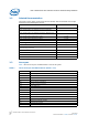
Intel® IXP43X Product Line of Network Processors—Hardware Design Guidelines Figure 31. DDR - Write Preamble/Postamble Duration TVB6 DQS TVA6 DQS Table 30. Symbol DDRII-400 MHz Interface -- Signal Timings Parameter Minimum Nominal Maximum Units Notes TVB1 DQ, CB and DM write output valid time before DQS. 521 ps 1 TVA1 DQ, CB and DM write output valid time after DQS. 521 ps 1 TVB3 Address and Command write output valid before CK rising edge.
Hardware Design Guidelines—Intel® IXP43X Product Line of Network Processors Table 31. DDR II/I SDRAM Interface -- Signal Timings Symbol Parameter Minimum Nom. Maximum Units Notes TVB1 DQ, CB and DM write output valid time before DQS. 1146 ps 1 TVA1 DQ, CB and DM write output valid time after DQS. 1146 ps 1 TVB3 Address and Command write output valid before CK rising edge. 3021 ps 1, 4 TVA3 Address and Command write output valid after CK rising edge.
Intel® IXP43X Product Line of Network Processors—Hardware Design Guidelines — Table 31 on page 79 Data Group to Strobe Summary: • The more restrictive data group to strobe timing occurs for read operations — Table 32 on page 80 — Table 33 on page 80 • The maximum allowable difference from any data group signal to the strobe is ±0.25 ns. — Figure 30 on page 77 — Table 32 on page 80 Strobe to Clock Summary: • The maximum allowable difference from any data strobe signal to the clock is 0.475 ns to +0.
Hardware Design Guidelines—Intel® IXP43X Product Line of Network Processors Table 33. Signal Package Lengths (Sheet 2 of 3) Group Data Control Signal Name Length (mil) Signal Name Length (mil) D_CB0 / DDR_CB0 402.94 D_CB4 / DDR_CB4 385.50 D_CB1 / DDR_CB1 393.93 D_CB5 / DDR_CB5 419.24 D_CB2 / DDR_CB2 377.69 D_CB6 / DDR_CB6 398.22 D_CB3 / DDR_CB3 378.47 D_CB7 / DDR_CB7 435.03 D_DQ0 / DDR_DQ0 447.57 D_DQ16 / DDR_DQ16 536.32 D_DQ1 / DDR_DQ1 449.41 D_DQ17 / DDR_DQ17 569.
Intel® IXP43X Product Line of Network Processors—Hardware Design Guidelines Table 33. Signal Package Lengths (Sheet 3 of 3) Group Command Signal Name Length (mil) Signal Name Length (mil) D_MA0 / DDR_MA0 515.78 D_MA7 / DDR_MA7 438.95 D_MA1 / DDR_MA1 357.69 D_MA8 / DDR_MA8 394.65 D_MA2 / DDR_MA2 509.12 D_MA9 / DDR_MA9 429.78 D_MA3 / DDR_MA3 462.16 D_MA10 / DDR_MA10 378.96 D_MA4 / DDR_MA4 444.71 D_MA11 / DDR_MA11 418.37 D_MA5 / DDR_MA5 576.87 D_MA12 / DDR_MA12 392.
Hardware Design Guidelines—Intel® IXP43X Product Line of Network Processors Figure 32. DDRII Clock Simulation Results: CK Signals Table 34. Clock Signal Group Routing Guidelines Parameter Definition Signal Group Members D_CK[2:0] and D_CK_N[2:0] Topology Differential Pair Point to Point (1 Driver, 4 Receivers) Single Ended Trace Impedance (Zo) Ω 33 Ω 50 Series Resistor Nominal Trace Width1 Nominal Pair Spacing (edge to edge) Internal (Strip Line) 3.
Intel® IXP43X Product Line of Network Processors—Hardware Design Guidelines internal layers, except for pin escapes. It is recommended that pin escape vias be located directly adjacent to the ball pads on all signals. Surface layer routing should be minimized. The following table provides routing guidelines for signals within these groups. Figure 33. DDRII Data and Control Simulation Results: DQ and DQS signals DQ 22 ohm DQS Table 35.
Hardware Design Guidelines—Intel® IXP43X Product Line of Network Processors Table 35. DDRII Data and Control Signal Group Routing Guidelines Parameter Definition Minimum Spacing to Other DDR Signals 20.0 mils Minimum Spacing to non-DDR Signals 25.0 mils Maximum Via Count 5 per trace Total Trace Length 1000 mils to 2000 mils Notes: 1. Nominal trace width is determined by board physical characteristics and stack-up. This value should be verified with the PWB manufacturer to achieve the desired Zo.
Intel® IXP43X Product Line of Network Processors—Hardware Design Guidelines Table 36. DDRII Command Signal Group Routing Guidelines Parameter Series Resistor Nominal Trace Width Definition 20 1 Nominal Pair Spacing (edge to edge) 2 Ω Internal (Strip Line) 3.5 mils, External (Micro Strip) 5 mils Internal (Strip Line) 10.5 mils, External (Micro Strip) 10 mils Minimum Pair to Pair Spacing Any layer 20mils Minimum Spacing to Other DDR Signals 20.0 mils Minimum Spacing to non-DDR Signals 25.