Intel® Q965 Express Chipset Development Kit User Manual October 2007 Order Number: 315664-002US
INFORMATION IN THIS DOCUMENT IS PROVIDED IN CONNECTION WITH INTEL® PRODUCTS. NO LICENSE, EXPRESS OR IMPLIED, BY ESTOPPEL OR OTHERWISE, TO ANY INTELLECTUAL PROPERTY RIGHTS IS GRANTED BY THIS DOCUMENT.
Intel Q965 Express Chipset— Contents 1.0 About This Manual .................................................................................................... 7 1.1 Content Overview ............................................................................................... 7 1.2 Text Conventions................................................................................................ 7 1.3 Glossary of Terms and Acronyms ..........................................................................
—Intel Q965 Express Chipset 4.6.1 4.6.2 5.0 Error 5.1 5.2 5.3 5.4 Installation of a new Operating System ..................................................... 45 Drivers Installation ................................................................................. 45 Messages and Beep Codes .............................................................................. 46 Speaker ...........................................................................................................
Intel Q965 Express Chipset— 23 24 25 26 27 Beep codes ..............................................................................................................46 Lists of error messages and brief description of each .....................................................47 Port 80h POST Code Ranges ......................................................................................47 Port 80h Progress Code Enumeration ..........................................................................
—Intel Q965 Express Chipset Revision History Date Revision Description October 2007 002 Change SDVOB to SDVOC in pins 58, 59, 62 and 63 in Table 9, “Intel® SDVO to PCI Express* connector mapping for MEC cards” on page 18. October 2006 001 Initial public release.
Intel Q965 Express Chipset—About This Manual 1.0 About This Manual This user’s manual describes the use of the Intel® Q965® Express Chipset Development Kit. This manual has been written for OEMs, system evaluators, and embedded system developers. All jumpers, headers, LED functions, and their locations on the board, along with subsystem features and POST codes, are defined in this document.
About This Manual—Intel Q965 Express Chipset Variables Variables are shown in italics. Variables must be replaced with correct values. Instructions Instruction mnemonics are shown in uppercase. When you are programming, instructions are not case-sensitive. You may use either upper-case or lower-case. Numbers Hexadecimal numbers are represented by a string of hexadecimal digits followed by the character H. A zero prefix is added to numbers that begin with A through F. (For example, FF is shown as 0FFH.
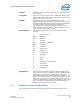
Intel Q965 Express Chipset—About This Manual Table 1. Glossary of Terms and Acronyms (Sheet 1 of 3) Term Description ADD2 Card Advanced Digital Display Card – second Generation. This card provides digital display options for an Intel Graphics Controller. It plugs into an x16 PCI Express* connector but uses the multiplexed SDVO interface. This Advanced Digital Display Card will not work with an Intel Graphics Controller that supports DVO and ADD cards.
About This Manual—Intel Q965 Express Chipset Table 1. Glossary of Terms and Acronyms (Sheet 2 of 3) Term Description Intel® VT Intel® Virtualization Technology. Intel® VT allows one hardware platform to function as multiple “virtual” platforms. For businesses, Intel VT Technology1 (Intel® VT) offers improved manageability, limiting downtime and maintaining worker productivity by isolating computing activities into separate partitions.
Intel Q965 Express Chipset—About This Manual Table 1. Glossary of Terms and Acronyms (Sheet 3 of 3) Term Description Rank A unit of DRAM corresponding to eight x8 SDRAM devices in parallel or four x16 SDRAM devices in parallel, ignoring ECC. These devices are usually, but not always, mounted on a single side of a DIMM. UMA Unified Memory Architecture. Describes an IGD using system memory for its frame buffers. Note: 1.
Development Kit Hardware Features—Intel Q965 Express Chipset 2.0 Development Kit Hardware Features 2.1 Overview This chapter provides information on the development kit features and the board capability. For detailed platform features please refer to the Platform Design Guide for or datasheet for the chipset and the Intel® Core™2 Duo processor Thermal and Mechanical Design Guidelines. 2.
Intel Q965 Express Chipset—Development Kit Hardware Features Table 3. 2.3 Development Kit Features Summary (Sheet 2 of 2) Form Factor 4 Layer μBTX (10.5 inches x 10.4 inches) Peripheral Interfaces Six SATA 1.5/3.0 Gb/s ports. Ten Universal Serial Bus (USB) 2.
Development Kit Hardware Features—Intel Q965 Express Chipset Figure 1. Dev Kit Board Main Components, Headers and Jumper Locations 2.3.1 Core Components Table 4.
Intel Q965 Express Chipset—Development Kit Hardware Features 2.3.2 Jumper Settings and Descriptions Table 5. Jumper Settings Jumper 2.3.
Development Kit Hardware Features—Intel Q965 Express Chipset Table 7.
Intel Q965 Express Chipset—Development Kit Hardware Features Figure 2. Rear Panel I/O Connectors E A K I H O J P B Table 8. D F M L G N Back panel connectors Callouts from Figure 2.2 2.3.
Development Kit Hardware Features—Intel Q965 Express Chipset Table 9. Intel® SDVO to PCI Express* connector mapping for MEC cards (Sheet 1 of 3) Pin Number Side B PCI Express* Function Side A SDVO/MEC Function 12 V PCI Express* Function PRSNT1# SDVO/MEC Function 1 12 V NC 2 12 V 12 V 12V 12V 3 RSVD RSVD 12V 12V 4 GND GND GND GND 5 SMCLK NC JTAG2 (TCK) NC 6 SMDAT NC JTAG3 (TDI) JTAG3 (TDI) 7 GND GND JTAG4 (TDO) JTAG4 (TDO) 8 3.3 V 3.
Intel Q965 Express Chipset—Development Kit Hardware Features Table 9.
Development Kit Hardware Features—Intel Q965 Express Chipset Table 9.
Intel Q965 Express Chipset—Development Kit Hardware Features Table 10. PCI Express* (x1) Pinout Pin Number Note: 2.3.8 Side B Side A 14 HSOP0 REFCLK- 15 HSON0 GND 16 GND HSIP1 17 PRSNT2# HSIN1 18 GND GND End of x1 Connector Front Panel Header (Power up & Reset) This development kit board use front panel header (J28LB) for powering-up and board reset. Refer to Table 11 for the front panel header lists. The front panel header is a 2x5 header, designated as J28LB.
Development Kit Hardware Features—Intel Q965 Express Chipset Table 12. Front Panel USB Header (Sheet 2 of 2) Pin Signal names 8 Ground 9 Key 10 USB_FP_OC0 Description Front panel USB over current signal (Ports 0,1) Note: +5 V Dual switches between +5 V and +5 V Standby depending on the current board state. 2.3.10 Front Audio Header The front panel Audio header is a 2x7 header, designated as J8AU. The following table outlines the pin out and functionality of this header: Table 13.
Intel Q965 Express Chipset—Development Kit Hardware Features Table 14. High Definition Audio Header (Sheet 2 of 2) Pin Signal Name 8 Description VCC3 Power 9 AUD_LINK_SDI0 10 +12V Power 11 AUD_LINK_SDI1 12 KEY 13 No Connect TP_AUD_LINK_SDO_1_HDR 14 V_3P3_STBY\G 15 AUD_LINK_SDI2_R 16 GND 3.3V Standby Ground 2.3.12 BTX Power Connectors Table 15. 2x12 BTX Power Connector Pin Table 16. Signal Name Pin Signal Name 1 +3.3V 13 GND 2 +3.
Development Kit Hardware Features—Intel Q965 Express Chipset 2.3.13 SATA Pinout Table 17. SATA Pinout Pin Signal Name 1 GND 2 TXP 3 TXN 4 GND 5 RXN 6 RXP 7 GND 2.3.14 Fan Connectors Table 18. Fan connectors 2.4 Pin Signal Name 1 GND 2 +12V 3 RPM 4 Control Thermal Considerations The development kit is shipped with a BTX TYPE I heatsink/fan thermal solution for installation on the processor.
Intel Q965 Express Chipset—Development Kit Hardware Features Figure 3.
Development Kit Software and BIOS Features—Intel Q965 Express Chipset 3.0 Development Kit Software and BIOS Features This chapter provides an overview of development kit software and BIOS features. 3.1 Software Key Features The software in the kit was chosen to facilitate development of real-time applications based on the components used in the evaluation board.
Intel Q965 Express Chipset—Development Kit Software and BIOS Features Table 19 lists the BIOS setup program menu features. Table 19. BIOS Setup Program Menu Bar Main Displays processor and memory configurations Table 20.
Development Kit Software and BIOS Features—Intel Q965 Express Chipset Using SMBIOS, a system administrator can obtain the system types, capabilities, operational status, and installation dates for system components. The MIF database defines the data and provides the method for accessing this information. The BIOS enables applications such as third-party management software to use SMBIOS.
Intel Q965 Express Chipset—Development Kit Software and BIOS Features 3.2.5.2 Network Boot The network can be selected as a boot device. This selection allows booting from the on-board LAN or a network add-in card with a remote boot ROM installed. In order to boot from the LAN you will have to enter the BIOS and select LAN boot as your first boot device. 3.2.5.
Development Kit Software and BIOS Features—Intel Q965 Express Chipset IEGD is created specifically for embedded platforms, offering an adaptable alternative to drivers designed for the desktop market segments. IEGD offers Intel's embedded customers extended life support that correlates with the extended life support of Embedded IA-32 silicon products.
Intel Q965 Express Chipset—Development Kit Software and BIOS Features — SSL3.1/TLS encryption — HTTP authentication — TCP/IP — HTTP web GUI — XML/SOAP API • Remote troubleshooting and recovery that can significantly reduce desk-side visits and potentially increase efficiency of IT technical staff.
Setting Up & Configuring the Development Kit—Intel Q965 Express Chipset 4.0 Setting Up & Configuring the Development Kit This chapter identifies the evaluation kit basic board’s set up and operation. Please refer to Chapter 2.0 for the board layout, jumper setting location and the component reference designator. 4.1 Overview The following hardware is included in the development kit: • One Intel® Q965 Express Chipset Development Kit reference board. • One Intel® Core™2 Duo processor E6400 2.
Intel Q965 Express Chipset—Setting Up & Configuring the Development Kit 4.2 Additional Hardware & Software Required Before you set up and configure your evaluation board, you may want to gather some additional hardware and software. VGA or LCD Monitor You can use any standard VGA or multi-resolution LCD monitor. The setup instructions in this chapter assume that you are using a standard VGA monitor. Keyboard You will need a PS/2 style or USB keyboard. Mouse You will need a PS/2 style or USB mouse.
Setting Up & Configuring the Development Kit—Intel Q965 Express Chipset 3. Check for damage that may have occurred during shipment. Contact your sales representative if any items are missing or damaged. Caution: Connecting the wrong cable or reversing the cable can damage the evaluation board and may damage the device being connected. Since the board is not in a protective chassis, use caution when connecting cables to this product. Caution: Standby voltage is constantly applied to the board.
Intel Q965 Express Chipset—Setting Up & Configuring the Development Kit The board and SRM assembly should look like the figure below. Figure 7.
Setting Up & Configuring the Development Kit—Intel Q965 Express Chipset Place the heatsink on top of the processor. The heatsink should align with the holes on the SRM and board as shown below in Figure 7. Please clean the surface of the processor with isopropyl alcohol before attaching the heatsink. Figure 8.
Intel Q965 Express Chipset—Setting Up & Configuring the Development Kit Use two 6-32 screws to partially tighten the rear end of the heatsink to the board and the SRM as shown in Figure 9. The screw uses the threaded holes of the SRM for retention. Figure 9.
Setting Up & Configuring the Development Kit—Intel Q965 Express Chipset Use two 6-32 nuts and two bolts to secure the front side of the heatsink to the SRM. The screw can be dropped from the top and use a nut at the bottom or the screw can be inserted from the base of the SRM into the heatsink (based on the accessibility of the system). Figure 10.
Intel Q965 Express Chipset—Setting Up & Configuring the Development Kit Tighten the screws at the rear end of the heatsink as shown in the figure below. Figure 11. Secure the read end of heatsink to the SRM Note: Please make sure all the screws are tightened before using the system. 8. Plug the processor heat sink fan into J3TH. 9. Connect the SATA drive through SATA cable into J24LB (SATA 0). Connect a power cable to the SATA drive. 10.
Setting Up & Configuring the Development Kit—Intel Q965 Express Chipset 19. Optional to connect an Ethernet cable to LAN MagJack connector at J18LB. 20. Connect a standard recommended BTX power supply to the board. Plug the BTX 2x12 connector into J2BV power supply header. Plug the BTX 2x2 12V connector into J1BV. 21. Press the J9LB Power Button to power up the board. Turn on the power to the monitor and evaluation board. Ensure that the fan sink on the processor is operating. 4.3.
Intel Q965 Express Chipset—Setting Up & Configuring the Development Kit 4.3.1.1 Dual Channel (Interleaved) Mode Configurations Figure 13 shows a dual channel configuration using two DIMMs. In this example, the DIMM 0 sockets of both channels are populated with identical DIMMs. Figure 13. Dual Channel (Interleaved) Mode Configuration with two DIMMs Figure 14 shows a dual channel configuration using three DIMMs.
Setting Up & Configuring the Development Kit—Intel Q965 Express Chipset Figure 15 shows a dual channel configuration using four DIMMs. In this example, the combined capacity of the 2x DIMMs in Channel A equals the combined capacity of the 2x DIMMs in Channel B. Also, the DIMMs are matched between DIMM 0 and DIMM 1 of both channels. Figure 15. Dual Channel (Interleaved) Mode Configuration with four DIMMs 4.3.1.
Intel Q965 Express Chipset—Setting Up & Configuring the Development Kit Figure 17 shows a single channel configuration using 3x DIMMs. In this example, the combined capacity of the 2x DIMMs in Channel A does not equal the capacity of the single DIMM in the DIMM 0 socket of Channel B. Figure 17. Single Channel (Asymmetric) Mode Configuration with 3x DIMMs 4.4 Audio Subsystem Configurations The board supports the Intel® High Definition Audio subsystem based on the ADI1988A or 1988B audio codec.
Setting Up & Configuring the Development Kit—Intel Q965 Express Chipset Table 21 describes the lists of back panel task. Table 21. Back panel task (Audio) Symbols 4.
Intel Q965 Express Chipset—Setting Up & Configuring the Development Kit 4.5.2 RJ-45 LAN Connector with Integrated LEDs Two LEDs are built into the RJ-45 LAN connector as shown in Figure 19. Table 22 describes the LED states when the board is powered up and the Gigabit LAN subsystem is operating. Figure 19. LAN Connector LED locations Table 22. LAN Connector LED status LED Left Right Color Green LED State Condition Off LAN link is not established. On LAN link is established.
Error Messages and Beep Codes—Intel Q965 Express Chipset 5.0 Error Messages and Beep Codes This chapter describes the various progress codes that are reported by the BIOS and the corresponding LED Codes. The LED codes are 8-bit quantities and can be used as Port 80 codes if the platform supports Port 80 capturing device. The higher nibble alone is used for a 4-bit LED. The Status code driver is responsible for translating the Standard Progress/Error code into a one-byte value.
Intel Q965 Express Chipset—Error Messages and Beep Codes Table 24. Lists of error messages and brief description of each Error Message 5.4 Explanation CMOS Battery low The battery may be losing power. Replace the battery soon. CMOS Checksum Bad The CMOS checksum is incorrect. CMOS memory may have been corrupted. Run Setup to reset values. Memory Size Decreased Memory size has decreased since the last boot. If no memory was removed, then memory may be bad.
Error Messages and Beep Codes—Intel Q965 Express Chipset Table 26.
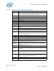
Intel Q965 Express Chipset—Error Messages and Beep Codes Port 80 code Progress Code Enumeration 0x70 Resetting the VGA controller 0x71 Disabling the VGA controller 0x72 Enabling the VGA controller Remote Console 0x78 Resetting the console controller 0x79 Disabling the console controller 0x7A Enabling the console controller Keyboard (PS2 or USB) 0x90 Resetting keyboard 0x9 Disabling the keyboard 0x9 Detecting the presence of the keyboard 0x9 Enabling the keyboard 0x9 Clearing keyboard
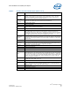
Error Messages and Beep Codes—Intel Q965 Express Chipset Port 80 code Progress Code Enumeration DXE Core 0xE4 Entered DXE phase 0xE5 Started dispatching drivers 0xE5 Started connecting drivers DXE Drivers 0xE7 Waiting for user input 0xE8 Checking password 0xE9 Entering BIOS setup 0xEA TBD – Flash Update 0xEB Calling Legacy Option ROMs 0xEE TBD – Calling Int 19. One beep unless silent boot is enabled.
Intel Q965 Express Chipset—Error Messages and Beep Codes Table 27.
Error Messages and Beep Codes—Intel Q965 Express Chipset October 2007 Order Number: 315664-002US Intel® Q965 Express Chipset DM 52