Intel® Desktop Board D101GGC Product Guide Order Number: D34587-001
Revision History Revision Revision History Date -001 First release of the Intel® Desktop Board D101GGC Product Guide October 2005 If an FCC declaration of conformity marking is present on the board, the following statement applies: FCC Declaration of Conformity This device complies with Part 15 of the FCC Rules.
Preface This Product Guide gives information about board layout, component installation, and regulatory requirements for Intel® Desktop Board D101GGC. Intended Audience The Product Guide is intended for technically qualified personnel. It is not intended for general audiences. Intended Uses All Intel desktop boards are evaluated as Information Technology Equipment (I.T.E.) for use in personal computers (PC) for installation in homes, offices, schools, computer rooms, and similar locations.
Intel Desktop Board D101GGC Product Guide Terminology The table below gives descriptions to some common terms used in the product guide.
Contents 1 Desktop Board Features Supported Operating Systems .............................................................................................. 10 Desktop Board Components ................................................................................................. 11 Processor .............................................................................................................................. 13 Main Memory ..........................................................................
Intel Desktop Board D101GGC Product Guide Installing and Removing Memory.......................................................................................... 31 Installing DIMMs........................................................................................................... 31 Removing DIMMs......................................................................................................... 33 Installing and Removing a PCI Express* x16 Card................................................
Contents 18. 19. 20. 21. 22. 23. 24. Internal Headers ............................................................................................................. 37 Back Panel Audio Connectors for Flexible 6-Channel Audio System ............................ 40 Location of Fan Headers ................................................................................................ 41 Connecting 2x12 Power Supply Cables .........................................................................
Intel Desktop Board D101GGC Product Guide viii
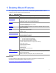
1 Desktop Board Features This chapter briefly describes the main features of Intel® Desktop Board D101GGC. Table 1 summarizes the major features of the desktop board. Table 1. Feature Summary Form Factor MicroATX (243.84 millimeters [9.60 inches] x 218.44 millimeters [8.60 inches]) Processor Support for an Intel® processor in the LGA775 package Main Memory • Two 184-pin, 2.
Intel Desktop Board D101GGC Product Guide Supported Operating Systems The desktop board supports the following operating systems: • Microsoft Windows* XP Media Center Edition 2005 • Microsoft Windows XP Professional • Microsoft Windows XP Professional x64 Edition • Microsoft Windows XP Home • Microsoft Windows 2000 10
Desktop Board Features Desktop Board Components Figure 1 shows the approximate location of the major components on desktop board D101GGC. Line In A B C D E W F G V H U T DIMM 0 DIMM 1 S I J R Q P O N M L K OM18207 Figure 1.
Intel Desktop Board D101GGC Product Guide Table 2.
Desktop Board Features Processor CAUTION Failure to use the appropriate power supply (below) and/or not connecting the 12 V (2x2) power connector to the desktop board may result in damage to the board, or the system may not function properly. Table 3. Power Supply Requirements Platform Compatibility Guide Power Supply Requirements 05A 12V2 rating of 13 A continuous and 16.5 A peak current for 10 ms 04A ATX12V (version 2.
Intel Desktop Board D101GGC Product Guide Related Links: Go to the following links or pages for more information about: • The latest list of tested memory, http://support.intel.com/support/motherboards/desktop/ • SDRAM specifications, http://www.intel.
Desktop Board Features Related Links: Go to the following link or pages for more information about: • Audio drivers and utilities http://support.intel.
Intel Desktop Board D101GGC Product Guide A B OM18208 Figure 2. LAN Connector LEDs Table 4 describes the LED states when the board is powered up and the 10/100 Ethernet LAN subsystem is operating. Table 4. RJ-45 10/100 Ethernet LAN Connector LEDs LED LED State Indicates A (Green) Off LAN link is not established On LAN link is established Blinking LAN activity is occurring Off 10 Mbits/s data rate is selected On (steady state) 100 Mbits/s data rate is selected B (Yellow) Hi-Speed USB 2.
Desktop Board Features Enhanced IDE Interface The IDE interface handles the exchange of information between the processor and peripheral devices like hard disks, CD-ROM drives, and Iomega Zip* drives inside the computer. The interface supports: • Up to four IDE devices (such as hard drives) • ATAPI-style devices (such as CD-ROM drives) • Older PIO Mode devices • Ultra DMA-33 /66/100/133 modes Serial ATA The desktop board supports four Serial ATA channels (1.5 Gb/s), connecting one device per channel.
Intel Desktop Board D101GGC Product Guide Security Passwords The BIOS includes security features that restrict whether the BIOS Setup program can be accessed and who can boot the computer. A supervisor password and a user password can be set for the BIOS Setup and for booting the computer, with the following restrictions: • The supervisor password gives unrestricted access to view and change all Setup options.
Desktop Board Features Fan Connectors The desktop board has a 4-pin processor fan header and two 3-pin chassis fan headers. See Figure 20 on page 41 for the location of the fan headers. Suspend to RAM (Instantly Available PC Technology) CAUTIONS For Instantly Available PC technology, the 5 V standby line for the power supply must be capable of delivering adequate +5 V standby current.
Intel Desktop Board D101GGC Product Guide CR1 OM18209 Figure 3. Location of the Standby Power Indicator Related Links: For more information on standby current requirements for the desktop board, refer to the Technical Product Specification by going to the following link, finding the product, and selecting Product Documentation from the left-hand menu: http://support.intel.com/support/motherboards/desktop/ Wake from USB NOTE Wake from USB requires the use of a USB peripheral that supports wake from USB.
Desktop Board Features Speaker A speaker is mounted on the desktop board. The speaker provides audible error code (beep code) information during the Power-On Self-Test (POST). Battery A battery on the desktop board keeps the values in CMOS RAM and the clock current when the computer is turned off. Go to page 46 for instructions on how to replace the battery. Real-Time Clock The desktop board has a time-of-day clock and 100-year calendar.
Intel Desktop Board D101GGC Product Guide 22
2 Installing and Replacing Desktop Board Components This chapter tells you how to: • Install the I/O shield • Install and remove the desktop board • Install and remove a processor and memory • Install and remove a PCI Express x16 card • Connect the IDE and Serial ATA cables • Connect internal headers • Set up flexible 6-channel audio with jack re-tasking • Connect fans and power cables • Locate other connectors • Set the BIOS configuration jumper • Clear passwords • Replace the battery Before You Begin CAU
Intel Desktop Board D101GGC Product Guide Installation Precautions When you install and test the Intel desktop board, observe all warnings and cautions in the installation instructions.
Installing and Replacing Desktop Board Components Installing the I/O Shield The desktop board comes with an I/O shield. When installed in the chassis, the shield blocks radio frequency transmissions, protects internal components from dust and foreign objects, and promotes correct airflow within the chassis. Install the I/O shield before installing the desktop board in the chassis. Place the shield inside the chassis as shown in Figure 4. Press the shield into place so that it fits tightly and securely.
Intel Desktop Board D101GGC Product Guide Installing and Removing the Desktop Board CAUTION Only qualified technical personnel should do this procedure. Disconnect the computer from its power source before performing the procedures described here. Failure to disconnect the power before you open the computer can result in personal injury or equipment damage. Refer to your chassis manual for instructions on installing and removing the desktop board.
Installing and Replacing Desktop Board Components Installing and Removing a Processor Instructions on how to install a processor to the desktop board are given below. Installing a Processor CAUTION Before installing or removing a processor, make sure the AC power has been removed by unplugging the power cord from the computer; the standby power LED should not be lit (see Figure 3 on page 20). Failure to do so could damage the processor and the board. To install a processor, follow these instructions: 1.
Intel Desktop Board D101GGC Product Guide 4. Remove the plastic protective socket cover from the load plate (see Figure 8, E). Do not discard the protective socket cover. Always replace the socket cover if the processor is removed from the socket. E OM17228 Figure 8. Remove the Protective Socket Cover 5. Remove the processor from the protective processor cover. Hold the processor only at the edges, being careful not to touch the bottom of the processor (see Figure 9).
Installing and Replacing Desktop Board Components 6. Hold the processor with your thumb and index fingers oriented as shown in Figure 10. Make sure fingers align to the socket cutouts (see Figure 10, F). Align notches (see Figure 10, G) with the socket see (Figure 10, H). Lower the processor straight down without tilting or sliding the processor in the socket. G G H F H F OM17214 Figure 10. Install Processor 7.
Intel Desktop Board D101GGC Product Guide Installing the Processor Fan Heat Sink Desktop board D101GGC has an integrated processor fan heat sink retention mechanism (RM).
Installing and Replacing Desktop Board Components Installing and Removing Memory NOTE To be fully compliant with all applicable Intel SDRAM memory specifications, the boards require DIMMs that support the Serial Presence Detect (SPD) data structure. You can access the PC Serial Presence Detect Specification at: http://www.intel.com/technology/memory/ddr/specs/dda18c32_64_128x72ag_a.pdf The desktop board has two 184-pin DIMM sockets arranged as DIMM 0 (blue) and DIMM 1 (black).
Intel Desktop Board D101GGC Product Guide 1. Observe the precautions in "Before You Begin" on page 23. 2. Turn off all peripheral devices connected to the computer. Turn off the computer and disconnect the AC power cord. 3. Remove the computer’s cover and locate the DIMM sockets (see Figure 14). A B DIMM 0 DIMM 1 OM18213 Figure 14. Installing a DIMM 4. Remove the PCI Express video card if it interferes with the DIMM retaining clips from being easily opened and closed. 5.
Installing and Replacing Desktop Board Components Removing DIMMs To remove a DIMM, follow these steps: 1. Observe the precautions in "Before You Begin" on page 23. 2. Turn off all peripheral devices connected to the computer. Turn off the computer. 3. Remove the AC power cord from the computer. 4. Remove the computer’s cover. 5. Remove the PCI Express card if it interferes with the DIMM clips from being easily opened and closed. 6. Gently spread the retaining clips at each end of the DIMM socket.
Intel Desktop Board D101GGC Product Guide Installing and Removing a PCI Express* x16 Card CAUTION When installing a PCI Express x16 card on the desktop board, ensure that it is fully seated in the PCI Express x16 connector before you power on the system. If the card is not fully seated in the PCI Express connector, an electrical short may result across the PCI Express connector pins. Depending on the over-current protection of the power supply, certain board components and/or traces may be damaged.
Installing and Replacing Desktop Board Components Connecting the IDE Cable The IDE cable can connect two drives to the desktop board. The cable supports the ATA-133 transfer protocol. Figure 16 shows the correct installation of the cable. NOTES ATA-133 compatible cables are backward compatible with drives using slower IDE transfer protocols.
Intel Desktop Board D101GGC Product Guide Connecting the Serial ATA (SATA) Cable The SATA cable (4-conductor) supports the Serial ATA protocol and connects a single drive to the desktop board. Either end of the cable can be connected to the SATA drive or the connector on the board. For correct cable function: 1. Observe the precaution in "Before You Begin" on page 23. 2. Attach the locking cable end to the connector (Figure 17, A) on the board. 3.
Installing and Replacing Desktop Board Components Connecting Internal Headers Before connecting cables to the internal headers, observe the precautions in "Before You Begin" on page 23. Figure 18 shows the location of the internal headers.
Intel Desktop Board D101GGC Product Guide Installing a Front Panel Audio Solution for Intel® High Definition Audio Figure 18, D on page 37 shows the location of the yellow front panel audio header. Table 5 shows the pin assignments for the front panel audio header. Table 5.
Installing and Replacing Desktop Board Components Connecting Hi-Speed USB 2.0 Headers Before connecting the USB 2.0 headers, observe the precautions in "Before You Begin" on page 23. See Figure 18, A on page 37 for the location of the black USB 2.0 headers. Table 7 shows the pin assignments for the headers. Table 7. Hi-Speed USB 2.
Intel Desktop Board D101GGC Product Guide Setting Up the Flexible 6-Channel Audio with Jack Re-tasking (Optional) After installing the Realtek audio driver, the multi-channel audio feature can be enabled. A B C OM18218 Item Description A Rear left/right out or Line In B Front left/right out or Line Out C Center/LFE (Subwoofer) or Mic In Figure 19.
Installing and Replacing Desktop Board Components Connecting Fan and Power Cables Connecting Fan Cables Figure 20 shows the location of the fan headers. Connect the processor’s fan heat sink cable to the 4-pin processor fan header on the board. Connect chassis fan cables to the 3-pin fan headers. 3 2 1 4 3 2 1 3 2 1 4 4 3 2 2 3 1 1 3 2 2 1 1 OM18219 Figure 20.
Intel Desktop Board D101GGC Product Guide Connecting Power Cables CAUTION Failure to use the appropriate power supply and/or not connecting the 12 V (2x2) power connector to the desktop board may result in damage to the board or the system may not function properly. See Table 3 on page 13 for power supply requirements. Figure 21 shows the location of the power connectors. 2X2 2 X 12 OM18220 Figure 21. Connecting 2x12 Power Supply Cables 1. Observe the precautions in "Before You Begin" on page 23. 2.
Installing and Replacing Desktop Board Components Other Connectors Figure 22 shows the location of the PCI bus add-in card, PCI Express x1, chassis intrusion, and diskette drive connectors. A B C E D OM18221 Item Description A PCI bus add-in card connector 2 B PCI bus add-in card connector 1 C PCI Express x1 connector D Chassis intrusion connector E Diskette drive connector Figure 22.
Intel Desktop Board D101GGC Product Guide Setting the BIOS Configuration Jumper NOTE Always turn off the power and unplug the power cord from the computer before changing the jumper. Moving the jumper with the power on may result in unreliable computer operation. Figure 23 shows the location of the desktop board’s BIOS configuration jumper block. 1 2 3 BR1 OM18222 Figure 23.
Installing and Replacing Desktop Board Components Table 9. Jumper Settings for the BIOS Setup Program Modes Jumper Setting Mode Description Normal (default) (1-2) The BIOS uses the current configuration and passwords for booting. Configure (2-3) After the Power-On Self-Test (POST) runs, the BIOS displays the Maintenance Menu. Use this menu to clear passwords. Recovery (None) The BIOS recovers data from a recovery diskette in the event of a failed BIOS update.
Intel Desktop Board D101GGC Product Guide Replacing the Battery A coin-cell battery (CR2032) powers the real-time clock and CMOS memory. When the computer is not plugged into a wall socket, the battery has an estimated life of three years. When the computer is plugged in, the standby current from the power supply extends the life of the battery. The clock is accurate to ± 13 minutes/year at 25 ºC with 3.3 VSB applied.
Installing and Replacing Desktop Board Components AVVERTIMENTO Esiste il pericolo di un esplosione se la pila non viene sostituita in modo corretto. Utilizzare solo pile uguali o di tipo equivalente a quelle consigliate dal produttore. Per disfarsi delle pile usate, seguire le istruzioni del produttore. PRECAUCIÓN Existe peligro de explosión si la pila no se cambia de forma adecuada. Utilice solamente pilas iguales o del mismo tipo que las recomendadas por el fabricante del equipo.
Intel Desktop Board D101GGC Product Guide AWAS Risiko letupan wujud jika bateri digantikan dengan jenis yang tidak betul. Bateri sepatutnya dikitar semula jika boleh. Pelupusan bateri terpakai mestilah mematuhi peraturan alam sekitar tempatan. OSTRZEŻENIE Istnieje niebezpieczeństwo wybuchu w przypadku zastosowania niewłaściwego typu baterii. Zużyte baterie należy w miarę możliwości utylizować zgodnie z odpowiednimi przepisami ochrony środowiska.
Installing and Replacing Desktop Board Components OСТОРОГА Використовуйте батареї правильного типу, інакше існуватиме ризик вибуху. Якщо можливо, використані батареї слід утилізувати. Утилізація використаних батарей має бути виконана згідно місцевих норм, що регулюють охорону довкілля.
Intel Desktop Board D101GGC Product Guide To replace the battery, follow these steps: 1. Observe the precautions in "Before You Begin" (see page 23). 2. Turn off all peripheral devices connected to the computer. Disconnect the computer’s power cord from the AC power source (wall outlet or power adapter). 3. Remove the computer cover. 4. Locate the battery on the board (see Figure 24). 5. With a medium flat-bladed screwdriver, gently pry the battery free from its connector.
A Regulatory Compliance This appendix contains the following regulatory compliance information for desktop board D101GGC: • Safety regulations • European Union Declaration of Conformity statement • Product Ecology statements • Electromagnetic Compatibility (EMC) regulations • Product certifications Safety Regulations Desktop board D101GGC complies with the safety regulations stated in Table 10 when correctly installed in a compatible host system. Table 10.
Intel Desktop Board D101GGC Product Guide European Union Declaration of Conformity Statement We, Intel Corporation, declare under our sole responsibility that the product Intel® Desktop Board D101GGC is in conformity with all applicable essential requirements necessary for CE marking, following the provisions of the European Council Directive 89/336/EEC (EMC Directive) and Council Directive 73/23/EEC (Safety/Low Voltage Directive).
Regulatory Compliance Slovensky Tento produkt je v súlade s ustanoveniami európskych direktív 89/336/EEC a 73/23/EEC. Slovenščina Izdelek je skladen z določbami evropskih direktiv 89/336/EGS in 73/23/EGS. Svenska Denna produkt har tillverkats i enlighet med EG-direktiv 89/336/EEC & 73/23/EEC. Türkçe Bu ürün, Avrupa Birliği’nin 89/336/EEC ve 73/23/EEC yönergelerine uyar. Product Ecology Statements The following information is provided to address worldwide product ecology concerns and regulations.
Intel Desktop Board D101GGC Product Guide Français Dans le cadre de son engagement pour la protection de l'environnement, Intel a mis en œuvre le programme Intel Product Recycling Program (Programme de recyclage des produits Intel) pour permettre aux consommateurs de produits Intel de recycler les produits usés en les retournant à des adresses spécifiées. Visitez la page Web http://www.intel.com/intel/other/ehs/product_ecology/Recycling_Program.
Regulatory Compliance Türkçe Intel, çevre sorumluluğuna bağımlılığının bir parçası olarak, perakende tüketicilerin Intel markalı kullanılmış ürünlerini belirlenmiş merkezlere iade edip uygun şekilde geri dönüştürmesini amaçlayan Intel Ürünleri Geri Dönüşüm Programı’nı uygulamaya koymuştur. Bu programın ürün kapsamı, ürün iade merkezleri, nakliye talimatları, kayıtlar ve şartlar v.s dahil bütün ayrıntılarını ögrenmek için lütfen http://www.intel.com/intel/other/ehs/product_ecology/Recycling_Program.
Intel Desktop Board D101GGC Product Guide Japanese Kanji statement translation: This is a Class B product based on the standard of the Voluntary Control Council for Interference from Information Technology Equipment (VCCI). If this is used near a radio or television receiver in a domestic environment, it may cause radio interference. Install and use the equipment according to the instruction manual.
Regulatory Compliance Product Certifications Board-Level Certification Markings Desktop board D101GGC has the product certification markings shown in Table 13: Table 13. Product Certification Markings Description Mark UL joint US/Canada Recognized Component mark. Includes adjacent UL file number for Intel desktop boards: E210882. FCC Declaration of Conformity logo mark for Class B equipment. Includes Intel name and D101GGC model designation. CE mark.
Intel Desktop Board D101GGC Product Guide Chassis and Component Certifications Ensure that the chassis and certain components; such as the power supply, peripheral drives, wiring, and cables; are components certified for the country or market where used. Agency certification marks on the product are proof of certification. Typical product certifications include: 58 • In Europe The CE marking signifies compliance with all applicable European requirements.