
Datasheet


Electrical Specifications
30 Intel
®
Itanium
®
Processor 9300 Series and 9500 Series Datasheet
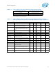
Notes:
1. Parameter value at full Intel
®
QPI Refclk.
2. Stagger offset = 0xF.
3. See Figure 2-6.
4. The termination small signal resistance; tolerance over the entire signalling voltage range shall not exceed ±5 ohms.
5. Requires Matlab script.
6. Refer to Intel
®
QuickPath Interconnect (Intel
®
QPI) - Electrical Specifications for calculation of this value. Note that UI to UI.
definition is used herein, where the value of UI-UI DCD = 2*UI DCD.
7. See Figure 2-7.
8. Applies to Vtx-diff-pp-pin.
9. Peak-to-peak value of the ripple.
TX
DUTY-CYCLE-PIN
Transmitter clock or data duty cycle at the
pin. Transmit duty cycle at the pin, defined as
UI to UI jitter as specified by the Intel
®
QPI
Electrical Specification, Rev 1.0.
-0.076 0.076 UI-UI 6
T
TX-DATA-CLK-SKEW-PIN
Delay of any data lane relative to clock lane,
as measured at Tx output
-0.5 0.5 UI 1,2
TX
ACC-JIT-N_UI-1E-9
Peak-to-peak accumulated jitter out of any TX
data or clock over 0<= n <= N UI where
N=12, measured with 1E-9 probability.
00.18UI5
TX
JITUI-UI-1E-9PIN
Transmitter clock or data UI-UI jitter at 1E-9
probability.
00.17UI5
RL
TX-DIFF
Transmitter Differential return loss from
50MHz to 2GHz
-10 dB 7
RL
TX-DIFF
Transmitter Differential return loss from
2GHz to 4GHz
-6 dB 7
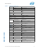
Table 2-6. Intel
®
Itanium
®
Processor 9300 Series Receiver Parameter Values for Intel
®
QuickPath Interconnect and Intel
®
SMI Channels @ 4.8 GT (Sheet 1 of 2)
Symbol Parameter Min Nom Max Units Notes
R
RX
RX termination resistance 37.4 47.6 Ω 3
T
Rx-data-clk-skew-pin
Delay of any data lane relative to the clock lane, as
measured at the end of Tx+ channel. This parameter is
a collective sum of effects of data clock mismatches in
Tx and on the medium connecting Tx and Rx.
-0.5 3.5 UI 2
T
Rx-data-clk-skew-pin
Delay of any data lane relative to the clock lane, as
measured at the end of Tx+ channel. This parameter is
a collective sum of effects of data clock mismatches in
Tx and on the medium connecting Tx and Rx.
0.48 0.52 UI 1
RL
RX-DIFF
Receiver differential return loss from 50 MHz to 2 GHz -10 dB 6
RL
RX-DIFF
Receiver differential return loss from 2GHz to 4GHz -6 dB 6
V
Rx-data-cm-pin
Receiver data common mode level 125 350 mV 2
V
Rx-data-cm-ripple-
pin
Receiver data common mode ripple 0 100 mV
p-p
V
Rx-clk-cm-pin
Receiver clock common mode level 175 350 mV
V
Rx-clk-cm-ripple-pin
Receiver clock common mode ripple 0 100 mV
p-p
V
RX-eye-data-pin
Minimum eye height at pin for data 200 mV 4
V
RX-eye-clk-pin
Minimum eye height at pin for clk 225 mV 5
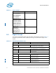
Table 2-5. Intel
®
Itanium
®
Processor 9300 Series Transmitter Parameter Values for
Intel
®
QuickPath Interconnect and Intel SMI Channels @ 4.8 GT/s (Sheet 2 of
2)
Symbol Parameter Min Nom Max Units Notes