
Note


Ball Usage
28 Application Note
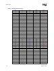
The test chip’s 0Ω measurements, listed in Table 7-3, can be used to generate tests that can detect 0
resistance between the two points, thus adding more open test coverage.
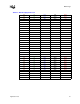
The test chip has VID_0-VID_5 signals pulled to VCCP with 1k resistors. Socket electrical
connections can be tested by measuring resistors between the respective electrical connections. The
following table can be used to generate tests that can detect 1k resistance between the two points,
thus adding more open test coverage. Rval from Table 7-4 identifies the resistor tolerance.
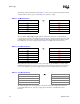
Each pull-down resistor can be used to verify connectivity of a ground ball and a control signal
ball. The following table can be used to generate tests that can detect 1k resistance between the two
points, thus adding more open test coverage. RvalControl from identifies the resistor tolerance.
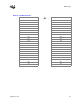
The following table can be used to generate tests that can detect 1k resistance between the two
points which will add more open test coverage. Rval from Table 6-1 identifies the resistor
tolerance.
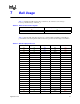
Table 7-3. 0Ω Measurements
Shorted Ball Shorted Ball
J1 D25
AA1 D26
AN4 AM4
AN3 AN8
F29 D28
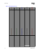
Table 7-4. 1kΩ Measurements
VID Ball Power Ball
AM2 AJ8
AL5 AG9
AM3 AH8
AL6 AF8
AK4 AF9
AL4 AG8
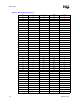
Table 7-5. 1kΩ Measurements
Control Resistor Ball GND Ball
E5
U1
D1 T3
E6 E8
D14 F7