
Guide

Intel
®
Celeron
®
D Processor for Embedded Applications Thermal Design Guide 19
Design Guidelines
2.1.3.2 Heatsink Attach Clip
2.1.3.2.1 Heatsink Attach Clip Usage
A heatsink attach clip holds the heatsink in place under dynamic loading and applies force to the
heatsink base. It serves to:
• Maintain desired pressure on the TIM for thermal performance.
• Ensure that the package does not disengage from the socket during mechanical shock and
vibration events (also known as package pullout).
• Protect solder joints from surface mount component damage during mechanical shock events
if no other motherboard stiffening device is used.
The heatsink clip is latched to the retention tab features at each corner of the retention mechanism
(see reference retention mechanism tab features in Appendix A, “Mechanical Drawings”).
2.1.3.2.2 Clip Structural Considerations
The heatsink attach clip must be able to support the mass of its corresponding heatsink during
mechanical stress testing. The clip must remain engaged with the retention mechanism tab features
and continue to provide adequate force to the heatsink base after mechanical stress testing for the
thermal interface material to perform as expected. Maximum load is constrained by the package
load capability, described in Section 4.8, “Package and Socket Load Specifications” on page 35.
The clip must designed in a way that makes it easy and ergonomic to engage with the retention
mechanism tabs without the use of special tools. The force required to install the clip (during clip
engagement to the retention mechanism tabs) shall not exceed 15 lbf. Clips that require more than
15 lbf to install may require a tool to make installation possible ergonomically.
2.1.3.2.3 Additional Clip Mechanical Design Guidelines
The heatsink clip must be designed in a way that minimizes contact with the motherboard surface
during clip attachment to the retention mechanism tab features; the clip must not scratch the
motherboard. All clip surfaces must be free of sharp edges to prevent injury to any system
component or to the person performing the installation.
2.1.3.3 Additional Requirements for Solutions Using Reference ATX Heatsink
and Reference Clip
This section defines the mechanical requirements for the interface between a processor
heatsink/fan/shroud assembly and the reference retention mechanism. These requirements are
intended to support interface control in the design of a custom thermal solution.
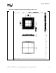
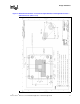
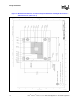
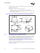
Requirement 1: Heatsink/fan/shroud assembly must stay within the volumetric keep-in defined in
Section 2.1.2, “Motherboard Volumetric Constraint Requirements” on page 12 and attach to the
Intel reference retention mechanism defined in Figure 15.
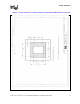
• Guideline: Rectangular heatsink base dimensions and tolerances:
— X-dimension = 2.70 ± 0.010 inch
— Y-dimension = 3.28 ± 0.010 inch
— Z-dimension: Inset in bottom surface of heatsink base in each of four corners shall hold a
z-dimension of 0.073 ± 0.010 inch