
Intel Celeron Processor on 0.13 Micron Process in the 478-Pin Package Datasheet

Intel
®
Celeron
®
Processor on 0.13 Micron Process in the 478-Pin Package Datasheet 23
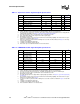
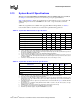
Electrical Specifications
I
SGNT
Islp
I
CC
Stop-Grant
2 GHz
2.10 GHz
2.20 GHz
2.30 GHz
2.40 GHz
2.50 GHz
2.60 GHz
2.70 GHz
2.80 GHz
18
23
23
23
23
23
23
23
23
A
9, 11, 12
I
TCC
I
CC
TCC active I
CC
A
8,
9
I
CC PLL
I
CC
for PLL pins 60 mA
9
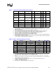
NOTES:
1. Unless otherwise noted, all specifications in this table are based on the latest silicon measurements available
at time of publication.
2. These voltages are targets only. A variable voltage source should exist on systems in the event that a different
voltage is required. See
Section 2.4 and Table 3 for more information. The VID bits will set the maximum VCC
with the minimum being defined according to current consumption at that voltage.
3. The voltage specification requirements are measured across VCC_SENSE
and VSS_SENSE
pins at the
socket with a 100 MHz bandwidth oscilloscope, 1.5 pF maximum probe capacitance, and 1 MΩ minimum im-
pedance. The maximum length of ground wire on the probe should be less than 5 mm. Ensure that external
noise from the system is not coupled in the scope probe.
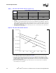
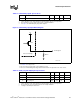
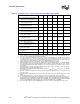
4. Refer to Table 8 and Figure 4 for the minimum, typical, and maximum VCC allowed for a given current. The
processor should not be subjected to any VCC and I
CC
combination wherein VCC exceeds V
CC
_MAX for a
given current. Moreover, VCC should never exceed the VID voltage. Failure to adhere to this specification
can affect the long term reliability of the processor.
5. V
CC
_MIN is defined at I
CC
_MAX.
6. FMB is the flexible motherboard guideline. These guidelines are estimates based on the data available at the
time of publication. FMB2 Guideline is calculated at VID of 1.525 V.
7. FMB1 guidelines intend to support both the Celeron processor on 0.13 micron process, and the Celeron pro-
cessor in the 478-pin package.
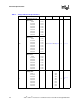
8. The maximum instantaneous current the processor will draw while the thermal control circuit is active as in-
dicated by the assertion of PROCHOT# is the same as the maximum I
CC
for the processor.
9. These specifications apply to processor with maximum VID setting 1.525 V.
10. Also applies to processors with fixed VID=1.525 V
11. The current specified is also for the AutoHALT State and applies to all frequencies.
12. I
CC
Stop-Grant and I
CC
Sleep are specified at V
CC
_MAX.
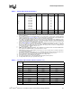
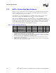
Table 8. VCC Static and Transient Tolerance (Sheet 1 of 2)
I
CC
(A)
Voltage Deviation from VID Setting (V)
1,2,3,4
Maximum Typical Minimum
0 0.000 –0.025 –0.050
5 –0.010 –0.036 –0.062
10 –0.019 –0.047 –0.075
15 –0.029 –0.058 –0.087
20 –0.038 –0.069 –0.099
25 –0.048 –0.079 –0.111
30 –0.057 –0.090 –0.124
35 –0.067 –0.101 –0.136
40 –0.076 –0.112 –0.148
45 –0.085 –0.123 –0.160
50 –0.095 –0.134 –0.173
Table 7. Voltage and Current Specifications
Symbol Parameter Min Typ Max Unit Notes
1